


Chapter 2 Operation
2-15
2.7 Loop Tuning
This section will help you adjust your control loop PID parameters to achieve a stable
deposition process. Keep in mind that there is no “best” way to determine PID
parameters, and no one set of settings that are “best.”
Setup System Parameters: Be sure that the output Scale and crystal Min/Max
Frequency parameters are accurate for your system. All Tooling parameters are best
set to 100% for now. A Period of .25 seconds is also a good starting point. Simulate
should be OFF.
Create a One-Layer Test Process: Create a new film with all default values. Create a
new process that has the new film as its only layer, and select it as the current process.
In the Quick Setup menu set Init Rate to your desired rate and Final Thickness to a
large value, say 10X your desired Final Thickness. Select the proper Sensor(s), Output,
and Material. Set Max Power to 100% and Slew rate to 100%.
Test the Setup: Press Auto/Manual to start the layer in Manual mode. Slowly turn the
control knob to a power of 10%, and verify that your power supply output is about 10%
of full scale. Continue to turn the control knob until a Rate(A/s) above 0 is shown.
Again, verify that the power supply output agrees with the SQC-122c Power(%) reading.
If the readings don’t agree, check your wiring and process setup. In particular, verify
that the System Parameters output scale agrees with your power supply input
specifications.
Determine Open Loop Gain: Slowly adjust the control knob until the Rate(A/s) reading
approximately matches your desired rate (Init Rate in the Quick Setup menu). Record
the desired rate Power(%) reading as PWR
DR
. Slowly lower the power until the
Rate(A/s) reading is just at (or near) zero. Record the zero rate Power(%) reading as
PWR
0R
.
Determine Open Loop Response Time: Calculate 1/3 of your desired rate (RATE
1/3
),
and 2/3 of the desired rate (RATE
2/3
) for this layer. Slowly increase the power until
Rate(A/s) matches RATE
1/3
. Get ready to record the loop’s response to an input
change. Quickly adjust Power(%) to PWR
DR
. Measure the time for the Rate (A/s)
reading to reach RATE
2/3
. You may want to do this several times to get an average
response time reading. Displaying the Rate graph will also help. Twice the measured
time is the step response time, TIME
SR
. TIME
SR
is typically .7 to 1.5 seconds for E-
Beam evaporation, 5 to 20 seconds for thermal evaporation.
Return the output power to 0%, then press Manual/Auto to return to Auto mode. Follow
these steps to set the loop PID parameters:
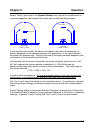
Set PID Values: In the Quick Setup menu set P=25, I= TIME
SR
, D=0. Exit the Quick
Setup menu. Press Start and observe the Power graph. The power should rise from
0%, and stabilize near PWR
DR
with little ringing or overshoot. If there is more than