


Chapter 2 Locations and Functions of Parts and Controls 2-3
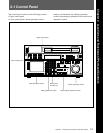
Chapter 2 Locations and Functions of Parts and Controls
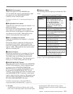
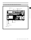
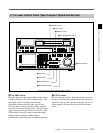
9 Indicator window
The following indicators light up to indicate the VTR’s
status.
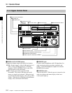
4 PHONES level control
Adjusts the output level to the PHONES jack.
You can enable this control to simultaneously adjust
the output level to the MONITOR OUTPUT
connectors on the connector panel.
For details, see Section 5-1-2, “Selecting Audio Signals” on
page 5-2.
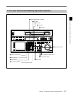
5 PB (playback) level controls
Adjust the level of the audio output for channels 1 to 4
and the cue channel.
Pull out the controls during playback to adjust the
audio output for each channel. Push in again for
factory-set levels (+4 dB output for a signal recorded
at a reference level of 0 dB). When pushed in, the
controls cannot adjust the audio output level.
6 REC (recording) level controls
Adjust the recording level for channels 1 to 4 and the
cue channel.
Pull out the controls to adjust the recording level for
each channel in E-E mode
1)
. Push in again for the
factory-set recording level (0 dB reference level for an
input of +4 dB). When pushed in, the controls cannot
adjust the recording level.
7 Audio level meters
Indicate the recording level in recording or E-E mode
or the playback level in playback or CONFI mode.
The display range can be changed by pressing the
DISPLAY FULL/FINE button. The reference level is
factory set at –20 dB, and the peak level at 0 dB.
8 MONITOR SELECT button
Selects the audio signal to be output at the MONITOR
OUTPUT L/R connector(s). Press to light the button
up, then press the AUDIO INPUT/MONITOR
SELECT button(s) to specify which channel(s) are to
be monitored at the MONITOR OUTPUT L or R
connector. If you specify more than one channel to the
same MONITOR OUTPUT connector, a mixed audio
signal is output from that connector. This specification
can also be done with setting the VTR SETUP menu
807~808 AUDIO MONITOR L~R select .
For details, see Section 4-6-3, “Selecting the Monitor
Output Signal (MON-L SEL/MON-R SEL)” on page 4-58.
1) E-E mode
An abbreviation for Electric-to-Electric mode. In this
mode, video or audio input signals are passed and output
..........................................................................................................................................................................................................
Indicator Status
Indicators and corresponding VTR status
CHANNEL
CONDITION
Indicates the playback signal condition.
Green: Playback signal is good.
Yellow: Playback signal is less than
good, but still reproducible.
Red: Playback signal is poor. Head
cleaning or internal inspection is
necessary if the indicator lights up
continuously.
INTERLACE Lights when the VTR is operating under
the interlace mode(50i/59.94i/60i).
PsF Lights when the VTR is operating under
the PsF mode(23.98PsF/24PsF/25PsF/
29.97PsF/30PsF).
23.98 Lights when the VTR is operating with a
frame frequency of 23.98 Hz.
25 Lights when the VTR is operating with a
frame frequency of 25 Hz.
24 Lights when the VTR is operating with a
frame frequency of 24 Hz.
29.97 Lights when the VTR is operating with a
frame frequency of 29.97 Hz.
only through the VTR’s internal circuitry, and not
through the magnetic conversion system comprising tape
and heads.
30
Lights when the VTR is operating with a
frame frequency of 30 Hz.
For more information about the selection of the frame
frequency , refer to the supplied Maintenance Manual.
ADV. AUDIO
Lights when item 821.AUDIO ADVANCE
MODE in the VTR SETUP menu is set to
“on.” When edit preset is set to “ON”, the
HDW-F500 operates internally with “off”
setting, so this indicator lights off.