


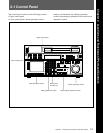
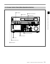

2-1 Control Panel
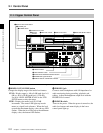
2-4 Chapter 2 Locations and Functions of Parts and Controls
Chapter 2 Locations and Functions of Parts and Controls
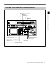
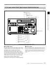
!º INPUT SELECT button
Selects the type and channel for the audio input signal.
Press to light the button up, then press one of the
AUDIO INPUT/MONITOR SELECT buttons to select
the type and the channel of the audio signal.
HD SDI (CH-1 to CH-4): Selects the input signal
from the HD SDI INPUT or SDTI (OPTION) IN
connector.
AES/EBU (CH-1 to CH-4): Selects signal input to
the AUDIO INPUT (AES/EBU) connectors.
ANALOG (CH-1 to CH-4): Selects signal input to
the AUDIO INPUT connectors.
The INPUT SELECT button will flash if there is no
incoming signal and HD SDI or AES/EBU is selected.
This setting can also be done with setting the VTR
SETUP menu 802~805 AUDIO INPUT select
CH1~CH4.
Notes
• When the signal input to the SDTI (OPTION) IN
connector is selected for the input video signal, the
signal input to the SDTI (OPTION) IN connector is
automatically selected for the input audio signal as
well.
• When the audio signal input to the SDTI (OPTION)
IN connector is selected for the input audio signal,
only the INPUT SELECT button lights.
For details, refer to “4-6-1 Selecting the Audio Input
Signal” on page 4-58.
!¡ AUDIO INPUT/MONITOR SELECT buttons
Select the audio input signal when the INPUT
SELECT button is lit, or the audio signal to be
monitored when the MONITOR SELECT button is lit.
!™ REF SYNC (reference signal) indicators
These indicate the signal selected as the reference
signal. If there is no reference signal input to the
selected connector, the STOP button flashes.
EXT SD: Is lit when the video signal input to the
REF. IN SD connector is acting as the reference
signal.
EXT HD: Is lit when the video signal input to the
REF. IN HD connector is acting as the reference
signal.
INPUT VIDEO: Is lit when the video signal input to
the HD SDI INPUT or SDTI (OPTION) IN
connector is acting as the reference signal.
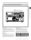
!£ REMOTE buttons and RS-232C indicator
Press these buttons to select external equipment to be
used to remotely control the VTR.
1(9 pin): Press to select the unit connected to the
REMOTE1-IN(9P)/OUT (9P) connectors. The
button lights up.
2(50 pin): Press to select the unit connected to the
PARALLEL I/O (50P) connector (with optional
BKDW-509). The button lights up.
RS-232C indicator: Lights up when the VTR is
communicating with the external equipment
connected to the RS-232C connector.
Note
When the VTR is being controlled by external
equipment connected to the REMOTE1-IN (9P) or
PARALLEL I/O (50P) connector, all tape transport
buttons and edit operation buttons are disabled, except
the STOP and EJECT buttons. You may also specify
the disabling or enabling of all buttons by setting
008.LOCAL FUNCTION ENABLE in the VTR
SETUP menu.