


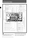


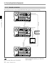

2-3 Connector Panel
2-16 Chapter 2 Locations and Functions of Parts and Controls
Chapter 2 Locations and Functions of Parts and Controls
!£ AUDIO INPUT LEVEL/600Ω termination
switches
The termination switches should be set for in
ANALOG AUDIO INPUT connector according to the
audio input level and input impedance.
Use OFF for low input levels when:
Audio input level is –60 dBu (microphone input)
and audio input impedance is high (approximately
20 kΩ)
Use OFF for high input levels when:
Audio input level is +4 dBu (line input) and audio
input impedance is high (approximately 20 kΩ)
Use ON for high input levels when:
Audio input level is +4 dBm (line input) and audio
input impedance is 600Ω
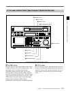
!¢ ANALOG AUDIO INPUT connectors
(XLR-3-32)
Accepts up to five analog audio signal lines (channels
1 to 4 and cue).
!∞ ANALOG AUDIO OUTPUT connectors
(XLR-3-31)
Outputs up to five analog audio signal lines (channels
1 to 4 and cue).
!§ CONTROL PANEL connector (15-pin)
Connects the control panel through the 15-pin cable
when using the control panel is used as a remote
controller.
!¶ REMOTE1-IN (9P)/OUT (9P) connectors
(D-sub 9-pin)
Used with the included 9pin remote control cable to
connect two HDW-F500 VTRs, or a second HD VTR
when a BVE900/910/2000/9000/9100 series BVE
Editing Control Unit is used for editing. Used when
you edit using two VTRs and the BVE-900/910/2000/
9000/9100 Editing Control Unit. The REMOTE1-IN
and OUT connectors can be used to make a bridge
connection.
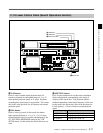
!• MONITOR OUTPUT connectors (XLR-3-31)
Outputs signals for audio monitoring. These
connectors output two signal lines: L and R. Select
the signals to be output with the MONITOR SELECT
buttons and the AUDIO INPUT/MONITOR SELECT
buttons on the upper control panel. A setting can be
made so that volume can be controlled with the
PHONES volume knob.
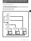
For details, see Section 5-1-2, “Selecting Audio Signals”on
page 5-2.
!ª VIDEO CONTROL (Digital Video Processor
Control) connector (D-sub 9-pin)
Connects to the optional HKDV-503 HD Digital Video
Controller to enable remote control of the internal
digital video processor. Turn off the power before
connecting the remote controller.
@º RS-232C connector (RS-232C serial interface)
(D-sub 25-pin)
Receives or transmits RS-232C serial remote control
signals and/or VTR status data from/to external
equipment. When this connector is being used for
communication, the RS-232C indicator on the upper
control panel will be lit.
@¡ PARALLEL I/O (50P) connector (D-sub 50-pin,
with optional BKDW-509)
Inputs an external remote control signal.
For details, refer to the Maintenance Manual.
@™ D CONV. SDI (D1/D2 SDI video/audio)
(OPTION) OUT connectors (BNC)
Outputs up to three sets of video/audio signals. When
the ALT/[F8] (CHARA SUPER) key of the TC menu
is set to ON, text data such as time codes are
superimposed on the output of connector 3 (SUPER).
Selection of D1/D2 output is made using the [F9]
(OTHERS CHECK)/[F9] (SYSTEM)/[F3] (D-CONV
SDI) button in the MAINTENANCE menu.
Note
This connector is operative only when the optional
HKDV-501A HD-SD Converter Board is installed.