


Chapter 2 Locations and Functions of Parts and Controls 2-15
Chapter 2 Locations and Functions of Parts and Controls
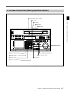
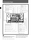
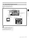
1 D CONV. OUT (OPTION) COMPOSITE
(SUPER) connector (BNC)
Outputs an analog composite signal for a video
monitor. When the ALT/[F6] (CHARA SUPER)
setting in the TC menu is on, character signals such as
time codes are superimposed on the output.
Note
This connector is operative only when the optional
HKDV-501A HD-SD Converter Board is installed.
2 D CONV. OUT (OPTION) SYNC connector
(BNC)
Outputs an NTSC external sync signal.
Notes
• This is effective only when the optional HKDV-501A
HD-SD Converter Board is installed.
• The phase is the same as the phase of the composite
signal output from the COMPOSITE (SUPER) of D
CONV. OUT (OPTION) connector. Because the
output phase changes with the operation mode of the
VTR, use this to synchronize with the video monitor.
3 REF. IN SD connectors (BNC) and 75 Ω
termination switch
Inputs for a reference video signal (NTSC or PAL) of
the selected field frequency. Use a video signal with
chroma burst (VBS) or a monochrome video signal
(VS).
A loop-through connection is possible. Set the 75 Ω
termination switch to OFF if you are using a loop-
through connection and set it to ON if you are not
using a loop-through connection.
4 REF. IN HD connectors (BNC) and 75 Ω
termination switch
Inputs for a reference video signal (HD) of the selected
field frequency. Use a trilevel SYNC signal for the
external synchronization. A loop-through connection
is possible. Set the 75 Ω termination switch to OFF if
you are using a loop-through connection and set it to
ON if you are not using a loop-through connection.
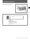
5 BREAKER button
Primary circuit breaker for the AC power circuit.
6 ⁄AC IN connector and connector
Connects to an AC outlet using the power cord
supplied with the VTR.
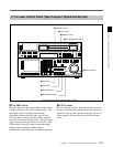
7 AUDIO INPUT (AES/EBU) connectors (BNC)
Inputs for digital signals in AES/EBU format for
channels 1 to 4.
8 AUDIO OUTPUT (AES/EBU)connectors (BNC)
Outputs digital signals in AES/EBU format for
channels 1 through 4.
9 HD SDI (SDI video/audio) INPUT connectors
(BNC)
The left connector accepts HD SDI video/audio
signals.
Note
The INPUT MONITOR connector is for use with an
input monitor and does not follow the standards for
output.
!º HD SDI (SDI video/audio) OUTPUT connectors
(BNC)
Outputs up to four (1 to 4) HD SDI video/audio signal
lines.
Character data such as time codes are superimposed on
the signal from the MONITOR connector when the
ALT/[F6] (CHARA SUPER) setting in the TC menu is
set.
!¡ SDTI (OPTION) IN connector (BNC)
Outputs a video/audio SDTI signal.
Note
This connector is operative only when the optional
HKDV-506A SDTI Board is installed.
!™ SDTI (OPTION) OUT connector (BNC)
Inputs a video/audio SDTI signal.
Note
This connector is operative only when the optional
HKDV-506A SDTI Board is installed.