


22 (GB) Chapter 1 Overview
Location and Function of Parts
Chapter 1 Overview
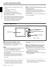
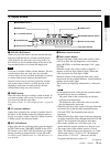
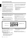
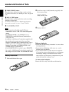
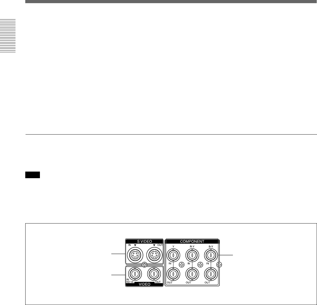
1 Video signal input/output section
1 S VIDEO connectors (4-pin)
Inputs/Outputs the S-video signal with Y (luminance)
and the C (chroma: 3.58 MHz for DSR-45 and 4.43
MHz for DSR-45P) separated.
2 VIDEO connectors (BNC-type)
VIDEO IN REF.IN (reference video / composite
video input) connector:
Inputs composite video signals to this unit. When
performing a playback synchronized with an
external sync signal, this connector inputs a
reference video (black burst) signal.
VIDEO OUT (composite video output) connector:
Outputs composite video signals. The data items
are not superimposed.
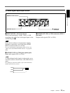
3 COMPONENT connectors (BNC-type)
Inputs/Outputs component video signals (Y/R-Y/B-Y).
2 VIDEO connectors
3 COMPONENT connectors
1 S VIDEO connectors
For details on the input and output of the wide-screen
aspect ratio information, see “Notes on Wide-screen
Aspect Ratio Information” on page 103 (GB).
Note
The unit can only accept standard video signals.
If you input the types of video signals shown below,
recorded picture, sound, and the EE picture output
via the VIDEO OUT, S VIDEO OUT and
COMPONENT OUT connectors may be distorted.
• Signals from some home game machines
• Blue background screen or gray background screen
from a consumer VCR
• Pictures played at a speed other than normal by a
VCR that does not have the TBC (Time Base
Corrector)
• Video signals in which the sync signals are distorted
• Signals from a defective cassette (tape or recording
condition is bad) played by an analog VCR that does
not have TBC
• If DV input has been selected, color and luminance
may be distorted in the EE mode, depending on the
monitor.
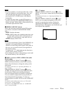
• The data items superimposed on a monitor connected
to this jack are the same as the items superimposed
on the LCD monitor.
You cannot make two monitors display different data
items individually.
• The adjustment of PB LEVEL on the VIDEO SET
menu does not affect the MONITOR VIDEO output.
• While the unit is externally synchronized, the sync
signal frequency and the burst signals of the video
signals output to the LCD monitor and the
MONITOR VIDEO jack are not synchronized.
Therefore, jitter may appear on those output signals.
If the unit is externally synchronized, use the VIDEO
OUT connector. If you use the MONITOR VIDEO
jack, set EXT SYNC on the VIDEO SET menu to
OFF.
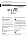
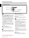
MONITOR AUDIO jack: Outputs the audio signals
for monitoring. Select the audio channels you
want to monitor as follows.
CH-1/2: channels 1/2
MIX: channels 1 to 4
CH-3/4: channels 3/4