16 (US)
Installing and Connecting the TV
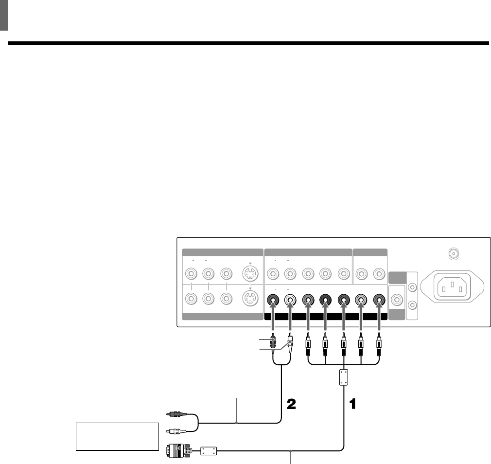
Connecting an RGB Equipment
Disconnect all power sources before making any connections.
1 Using an RGB cable, connect the RGB equipment’s video/synchronized
signal output terminal to the Y/G, P
B/B, PR/R, HD, and VD jacks on the
TV. Use the COMPONENT VIDEO IN 2/RGB IN connections.
2 Using an AUDIO cable, connect the RGB equipment’s AUDIO OUT
jacks to the TV’s AUDIO IN jacks. Be sure to use the same row of inputs
that you used for the video connection (COMPONENT VIDEO IN 2/
RGB IN).
Rear of TV
HD VD
IN
OUT
P
B
/BY/G P
R
/R
LR
AUDIO
LR
VHF/UHF
AC IN
AUDIO OUT
COMPONENT VIDEO IN 2
/
RGB IN
SUB
WOOFER
CONTROL
S
VIDEO
LR
AUDIO
P
B
YP
R
LR
AUDIO
S VIDEO
VIDEO IN 1 COMPONENT VIDEO IN 1
VIDEO IN 2
AUDIO-R (red)
AUDIO-L (white)
To the video/
synchronized signal
output terminal
SMF-403
(not supplied)
To the audio
output jacks
RK-74A
(not supplied)
RGB equipment


