3-1
PFM-42B1, PFM-42B1E
Section 3
Electrical Adjustments
3-1. Equipment Required
. Oscilloscope
Tektronix 2465 or equivalent
(band width : 350 MHz or more)
. VG (Programmable video signal generator)
VG814 or equivalent
. Frequency counter
Advantest TR5821AK or equivalent
. Digital voltmeter
Advantest TR6845 or equivalent
. Potential transformer
. Regulated DC power supply
. Remote commander (RM-42B)
Note : Perform the following adjustments at least 5 minutes after turning on
the power.
3-2. Electrical Adjustments Using the
Service Mode
The electrical adjustments can be performed using the remote
commander RM-42B supplied with the PFM-42B1/B1E. The
remote commander has the Service Mode. Select the Service
Mode to perform the electrical adjustments as listed below.
rr
rr
r Service Menu
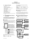
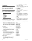
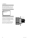
When you enter the Service Mode, the mode menu appears
as shown below. The mode menu contains the three menus
of MAIN MENU, SERVICE MENU and MANUAL
MENU as shown. Select the SERVICE MENU to perform
the electrical adjustments.
How to enter the Service Mode using the RM-42B:
In the STAND-BY state, press the keys in the following
order.
[DISPLAY] → [5] → [BRT+] → [
ON
]
How to enter the Service Mode using the commanders
other than RM-42B:
In the STAND-BY state, press the keys in the following
order.
[DISPLAY] → [5] → [
VOL+
] → [
POWER
]How to exit the
Service Mode :
Press the ON key once and back on to enter the STAND-BY
state or turn off the main power to exit the Service Mode.
rr
rr
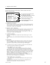
r Operation of remote commander in the
Service Mode
The four keys of MENU, ENTER, SELECT+ and SE-
LECT_ are the basic operation keys in the same manner as
in the user adjustment. The other keys can be operated in
the same manner as in the user adjustment.
rr
rr
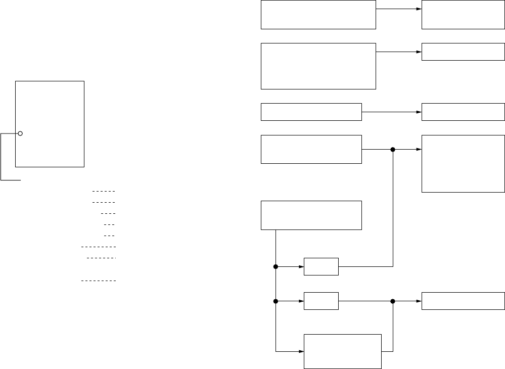
r The electrical adjustments using the Service
Mode become necessary in the following
cases.
When any of the following repairs is performed, adjust-
ment using the service mode becomes necessary.
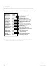
MODE SELECT
MAIN MENU
SERVICE MENU
MANUAL MENU
SERVICE MENU
EEPROM RESET
WHITE BALANCE
ADC CALIBRATION
VIDEO PROCESSOR
SPECIAL FUNCTION
PRESET EDIT
MAINTENANCE
STATUS/TEST
Initialization of EEPROM
Gain adjustment of digital gamma circuit
Calibration of A/D converter
Level adjustment of video processor circuit
Setting the special functions
Editing the preset signals
Setting the data that are unique
to the particular machine
Internal status and function test
: This is the user’s menu. Use the
MAIN MENU when user adjustment items
such as operation checks upon completion
of adjustments, are going to be made.
: This is the menu that is used for electrical
adjustments. This section of this manual
describes how to use the SERVICE MENU.
: This menu is used in production factory.
Do not make any attempts to use this menu
and do not make any operations using this menu.
Operation check only
When IC200 and its peripheral
parts (the parts that are
shown in schematic diagram
B (2/14) ) are replaced.
When PDP is replaced.
STATUS/TEST
B board
Power supply board
(APS-132 M)
When memory (IC511) on
the B board is replaced.
WHITE BALANCE
ADC CALIBRATION
ADC CALIBRATION
WHITE BALANCE
EEPROM RESET
WHITE BALANCE
ADC CALIBRATION
MAINTENANCE
STATUS/TEST
S1 board
When any of the following
boards is replaced.
When any repairs that
are related to picture quality
are performed.


