3-6
PFM-42B1, PFM-42B1E
6. PRESET EDIT
Preset Data Configuration
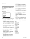
Memory map of the preset data area is shown in Table 1
(PROG. PRESET/FIXED PRESET). The areas from 1 to
20 are assigned to store the additional signal. The areas
from 21 to 74 are assigned to store the internal signal.
Menu Structure
How To Edit The Preset Data
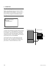
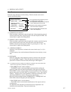
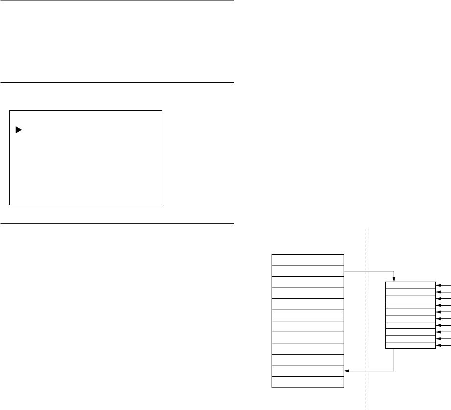
As shown in the illustration, the system controller contains
the memory area (i.e., Editing RAM) that is assigned only
for data editing. The source data that is used for editing
must be firstly copied to the Editing RAM. Edit then the
copied data as desired. Finally save the result of editing in
the specified preset area of the EEPROM.
(The illustration shows an example that the data in the
preset area No. 02 is once copied to the Editing RAM
where data is edited. The edited data is sent back to the
preset area No. 11 where the edited data is saved.)
PRESET EDIT
ORIGINAL DATA SELECT
DATA EDIT
SAVE AREA SELECT
EEPROM Preset areas System controller
Preset Area 01
Preset Area 02
Preset Area 03
Preset Area 04
Preset Area 05
Preset Area 06
Preset Area 07
Preset Area 08
Preset Area 09
Preset Area 10
Preset Area 11
Preset Area 12
Editing RAM
Editing


