


FIVE Monitor Functional Description 4.6
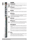
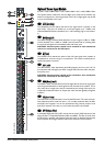
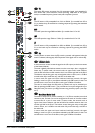
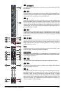
OOppttiioonnaall SStteerreeoo IInnppuutt MMoodduullee
The optional Stereo module has Left and Right input XLRs and the module may
either be configured as a stereo signal path or the Left or Right signals may be fed
in mono to both sides of the input.
1
SSEENNSS ((SSeennssiittiivviittyy))
The SENSitivity Control adjusts the level of the signal which is present on the
Input XLRs. The input can handle mic or line level signals up to +30dBu, with
individual RANGE switches (see below) for L and R selecting high or low sensitivi-
ty.
2
RRNNGG ((RRaannggee)) LL//RR
The RNGE (Range) switches selects between an input range of -2dBu to -70dBu
(switch released), and +10dBu to -20dBu (switch pressed and lit), enabling both
mic and line level signals to be handled by each side of the input.
CAUTION: Phantom power should not be switched on when unbalanced
sources are connected to the XLR inputs.
3
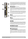
ØØ ((PPhhaassee))
The PHASE switch reverses the phase of the Left input signal when pressed, to
compensate for incorrect wiring or mic placement. The switch is internally illumi-
nated when phase is reversed.
4
4488VV LL aanndd RR
The 48V switches, when depressed, place 48V phantom power on pins 2 & 3 of
the respective Left and Right input XLRs. Integral LEDs illuminate when the phan-
tom power is on.
CAUTION: Phantom power should not be switched on when unbalanced
sources are connected to the XLR inputs.
5
MMNNOO ((MMoonnoo)) LL aanndd RR
The MNO L and R switches select the Left or Right sides of the source signal (post
input amp) and feeds either or both signals to both channels of the module. This is
very useful when a single mono source is attached to just one leg of the input, but
is required to feed both sides of an Output pair which has been globally configured
as Stereo.
6
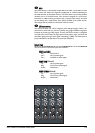
IINNSS ((IInnsseerrtt PPooiinntt))
The Insert Point may be switched in circuit by the INS switch. The insert uses sep-
arate balanced jacks for send and return. It is normally positioned after the filter
and before the equaliser, but can be repositioned using internal jumpers to be
post-EQ if required. The insert is in-circuit when the switch is illuminated.
7
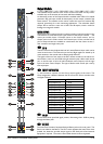
HHPPFF ((HHiigghhppaassss FFiilltteerr))
A sweepable High-pass Filter (HPF) control sets the cutoff (-3dB) frequency of the
High-pass filter: it is adjustable between 20Hz and 600Hz. The filter is active when
the IN switch is pressed, and bypassed when the switch is released, allowing easy
A/B comparison of the signal with and without the extreme low end content.
24-bus console