


FIVE Monitor Functional Description 4.16
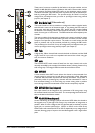
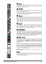
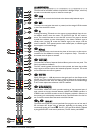
LL && RR OOUUTTPPUUTT SSEECCTTIIOONN
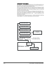
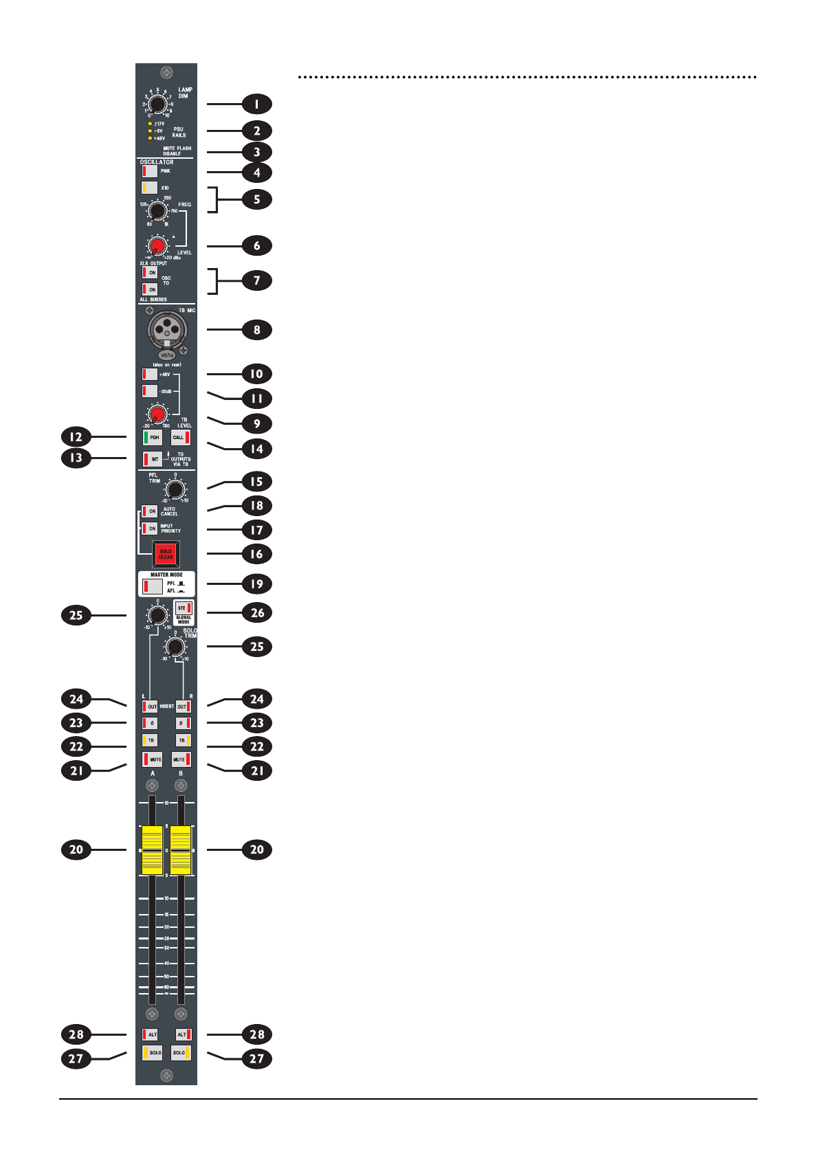
The lower half of the Master module comprises the Left/Right Output, which may
be used as two individual outputs or linked as a stereo pair.
p
FFAADDEERR
The 100mm fader controls the final level to the electronically balanced output.
a
MMUUTTEE
The output is muted when the switch is pressed, and the integral LED illuminates
to show that the MUTE is active.
s
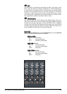
TTBB
Pressing the latching TB switch arms the output to receive talkback from the cen-
tral talkback section, when the master TO OUTPUTS VIA TB INT switch is
active. The switch illuminates to warn that OSC is armed. The output is dimmed
by 6dB when talkback is active. Alternatively, if the Master Talkback signal is
already active, pressing TB routes the Talkback signal to the output, until the
switch is released. TB is injected post the meter takeoff point, so talkback signals
do not appear on the meterbridge.
d
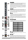
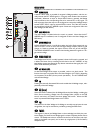
ØØ ((PPhhaassee))
Pressing the Ø (Phase) switch reverses the phase of the output, to allow experi-
mentation for best feedback immunity with a multiple-mic setup. The switch is
illuminated when the phase is reversed.
f
IINNSSEERRTT ((OOUUTT))
The Insert Point consists of separate Send and Return jacks on the rear panel. The
Send is normalled to the Return.
The OUT switch bypasses the Insert Point when pressed, but leaves the pre-fade
output signal on the Send jack to feed external equipment if required. The switch
is illuminated when the insert is bypassed.
g
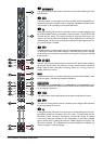
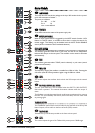
SSOOLLOO TTRRIIMM
SOLO TRIM gives +/- 10dB adjustment to the signal sent from that Output to the
AFL/PFL bus. This is useful for trimming a number of Outputs of varying levels to
give a consistent monitor level, thus reducing the requirement for manual Wedge
or ALT master adjustments whenever a SOLO is selected.
h
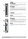
GGLLOOBBAALL MMOODDEE ((SSTTEE))
The GLOBAL MODE STE switch provides switching of the associated pairs of
send controls on the input channels between MONO and STEREO operation. In
STEREO mode, the SOLO switches on the L/R Outputs are linked in software, so
that pressing one automatically activates the other. See SOLO below for informa-
tion on how this switch affects the sends to the SOLO busses.
j
&&
k
SSOOLLOO // AALLTT
The SOLO switch feeds the pre and post-fade Group signal to one of two sets of
PFL and stereo AFL busses: Main or Alternate, depending on the setting of the
mechanically latching ALT switch
k
. The PFL / AFL state of the SOLO is affected
by the global PFL/AFL mode switch (see above). The PFL feed is post-INSERT.