


FIVE Monitor Functional Description 4.10
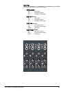
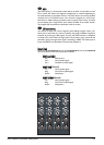
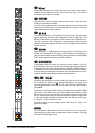
OOuuttppuutt MMoodduullee
The standard Output sections of the 24 and 32 bus frame sizes are very similar,
and differ only in the omission of one switch and Matrix labelling.
An alternative version of the Output Module is available which offers a full 4-band
parametric EQ (see Input module for description) on each output, instead of the
Matrix section. This module can be used to reduce the amount of external EQ
required, particularly for in-ear monitoring applications. The redundant Matrix
Output XLR is used for a mono sum of the A and B outputs, which is useful for
feeding an on-stage sub-woofer.
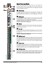
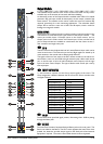
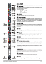
MMAATTRRIIXX OOUUTTPPUUTTSS
The Matrices are controlled via the upper section of the Output modules - one
matrix per module, hence 12-Output matrix on the 24-bus version, and 16-
Output matrix on the 32-bus version. An External Input, L/R bus, and the first 10
pairs of Output busses are available as contributions into the matrix via the 11
dual- concentric and single mono pots.
1
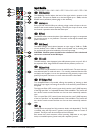
EEXXTT IINN
The EXT IN level control adjusts the level of a stereo External Input which can be
mixed to each matrix. The External input Left and Right signals are shared by all
matrix sections in the console and are electronically balanced.
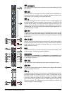
The signal is fed one of two ways to the EXT receive controls on the matrix sec-
tions: either a mono sum of the left and right external inputs is fed to each receive
pot, or the left input is fed to all odd numbered matrix Outputs, and the right
input to all even matrix Outputs. The type of feed to each receive pot is set by
internal jumpers.
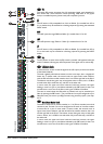
2
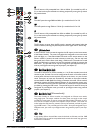
GGRROOUUPPSS MMIIXX TTOO MMAATTRRIIXX
11 dual-concentric controls mix the Group output signals to the matrix. The
Group assignment is different between the 24-bus and the 32-bus consoles and is
arranged as follows:
24-bus version 32-bus version
Group Outputs 1/2 1A/1B
Group Outputs 3/4 2A/2B
Group Outputs 5/6 3A/3B
Group Outputs 7/8 4A/4B
Group Outputs 9A/B 5A/5B
Group Outputs 10A/B 6A/6B
Group Outputs 11A/B 7A/7B
Group Outputs 12A/B 8A/8B
Group Outputs 13A/B 9A/9B
Group Outputs 14A/B 10A/10B
Group Outputs L/R L/R
Ext Input Ext Input
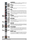
3
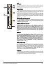
SSIIGG LLEEDD
The SIG LED shows post-fade signal present, illuminating when -30dB is passing
through the Matrix path.
4
IINNSS ((OOUUTT))
The Insert Point consists of separate Send and Return jacks on the rear panel. The
Send is normalled to the Return. The OUT switch bypasses the Insert Point when
pressed, but leaves the pre-fade output signal on the Send jack to feed external
equipment if required. The switch is illuminated when the insert is bypassed.