


Functional Description
21
SLES140A—March 2007 TVP5147M1PFP
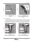
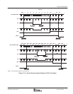
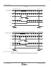
NTSC 601 64
PAL 601
10-Bit (PCLK = 2× Pixel Clock)
64
Mode B/2
First Field B/2
858
864
H/2
32
20-Bit (PCLK = 1× Pixel Clock)
32
B/2
429
432
H/2
HS
VS
Second Field
HS
VS
B/2
H/2 + B/2 H/2 + B/2
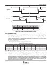
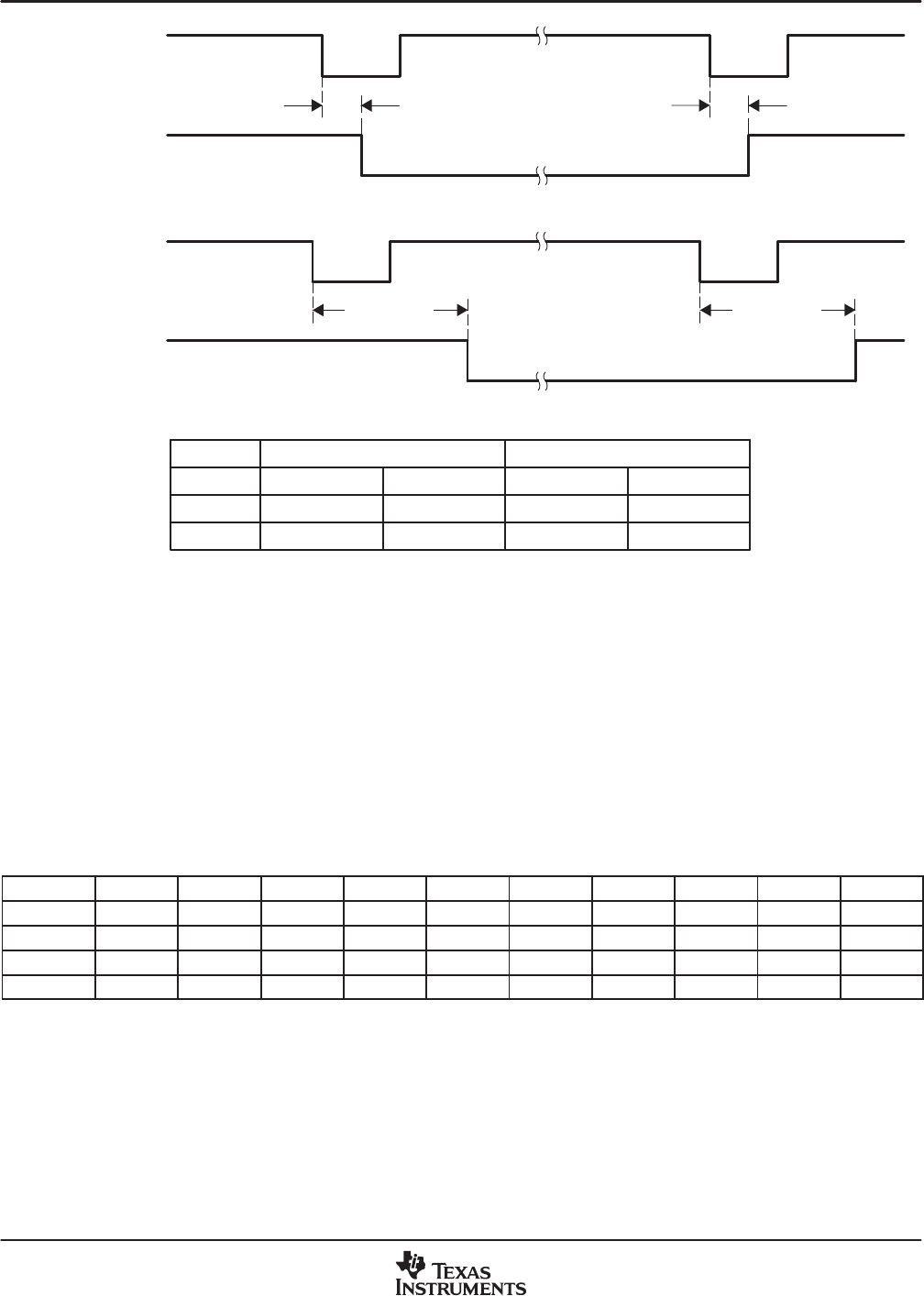
Figure 2−16. VSYNC Position With Respect to HSYNC
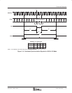
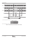
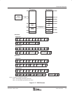
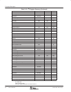
2.5.2 Embedded Syncs
Standards with embedded syncs insert the SAV and EAV codes into the data stream on the rising and falling
edges of AVID. These codes contain the V and F bits which also define vertical timing. Table 2−3 gives the
format of the SAV and EAV codes.
H equals 1 always indicates EAV. H equals 0 always indicates SAV. The alignment of V and F to the line and
field counter varies depending on the standard.
The P bits are protection bits:
P3 = V xor H; P2 = F xor H; P1 = F xor V; P0 = F xor V xor H
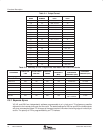
Table 2−3. EAV and SAV Sequence
D9 (MSB) D8 D7 D6 D5 D4 D3 D2 D1 D0
Preamble 1 1 1 1 1 1 1 1 1 1
Preamble 0 0 0 0 0 0 0 0 0 0
Preamble 0 0 0 0 0 0 0 0 0 0
Status word 1 F V H P3 P2 P1 P0 0 0
2.6 I
2
C Host Interface
Communication with the TVP5147M1 decoder is via an I
2
C host interface. The I
2
C standard consists of two
signals, the serial input/output data (SDA) line and the serial input clock line (SCL), which carry information
between the devices connected to the bus. A third signal (I2CA) is used for slave address selection. Although
an I
2
C system can be multimastered, the TVP5147M1 decoder functions as a slave device only.
Because SDA and SCL are kept open-drain at a logic-high output level or when the bus is not driven, the user
must connect SDA and SCL to a positive supply voltage via a pullup resistor on the board. The slave addresses
select signal, terminal 37 (I2CA), enables the use of two TVP5147M1 devices tied to the same I
2
C bus,
because it controls the least significant bit of the I
2
C device address.