Functional Description
30
SLES140A—March 2007TVP5147M1PFP
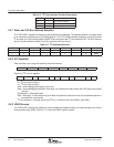
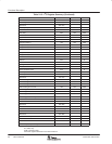
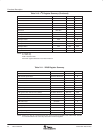
Table 2−10. I
2
C Register Summary (Continued)
REGISTER NAME I
2
C SUBADDRESS DEFAULT R/W
VBUS data access with no VBUS address increment E0h 00h R/W
VBUS data access with VBUS address increment E1h 00h R/W
FIFO read data E2h R
Reserved E3h−E7h
VBUS address access E8h−EAh 00 0000h R/W
Reserved EBh−EFh
Interrupt raw status 0 F0h R
Interrupt raw status 1 F1h R
Interrupt status 0 F2h R
Interrupt status 1 F3h R
Interrupt mask 0 F4h 00h R/W
Interrupt mask 1 F5h 00h R/W
Interrupt clear 0 F6h 00h R/W
Interrupt clear 1 F7h 00h R/W
Reserved F8h−FFh
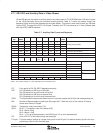
NOTE: R = Read only
W = Write only
R/W = Read and write
Reserved register addresses must not be written to.
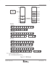
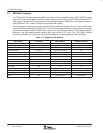
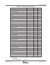
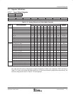
Table 2−11. VBUS Register Summary
REGISTER NAME I
2
C SUBADDRESS DEFAULT R/W
Reserved 00 0000h−80 051Bh
VDP closed caption data 80 051Ch−80 051Fh R
VDP WSS data 80 0520h−80 0526h R
Reserved 80 0527h−80 052Bh
VDP VITC data 80 052Ch−80 0534h R
Reserved 80 0535h−80 053Fh
VDP V-Chip data 80 0540h−80 0543h R
Reserved 80 0544h−80 05FFh
VDP general line mode and line address 80 0600h−80 0611h 00h, FFh R/W
Reserved 80 0612h−80 06FFh
VDP VPS (PDC)/Gemstar data 80 0700h−80 070Ch R
Reserved 80 070Dh−90 1903h
VDP FIFO read 90 1904h R
Reserved 90 1905h−A0 005Dh
Analog output control 2 A0 05Eh B2h R/W
Reserved A0 005Fh−B0 005Fh
Interrupt configuration B0 0060h 00h R/W
Reserved B0 0061h−FF FFFFh
NOTE: Writing any value to a reserved register may cause erroneous operation of the TVP5147M1 decoder.
It is recommended not to access any data to/from reserved registers.


