37
Connecting your TV
Selecting the AV output mode
You can select the AV output from three modes; ATV, DTV or
Monitor.
1 From AV Connection menu, press V or U to select AV
Output.
2 Press Y or Z to select the desired output mode.
ATV: Selected programmed channel from Analog
TV system is output from the AV OUTPUT
terminal.
DTV: Selected programmed channel from Digital
TV system is output from the AV OUTPUT
terminal.
Monitor: The AV output depends on the selected video
input mode.
(e.g. If o1 is selected (- page 25), the AV
signal input to o1 is output from the AV
OUTPUT terminal.
Note:
When it is set to Monitor (and in DTV mode) or DTV, and the
digital program is locked, the output will be blank and audio
will be muted.
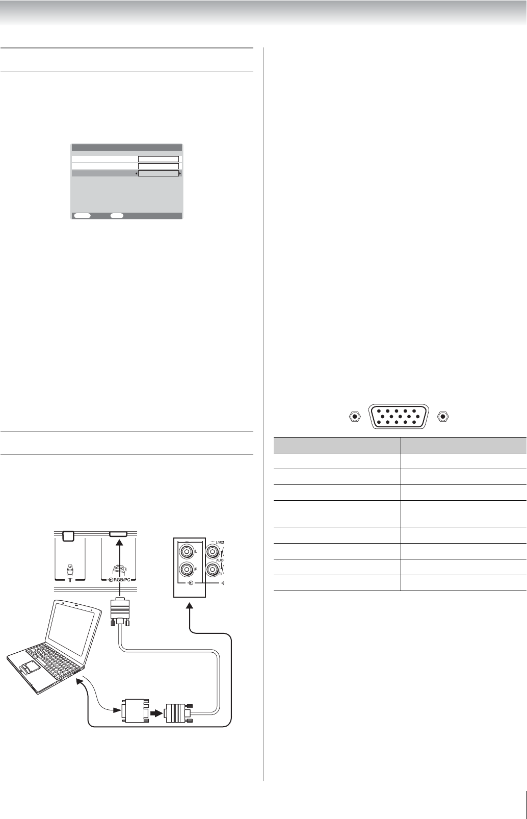
Connecting a computer
To connect a PC to the RGB/PC terminal on the TV:
An analog RGB (15 pin) computer cable can be connected.
Connect a PC cable from the computer to the o RGB/PC
terminal on the back of the TV.
The following signals can be displayed:
• VGA: VESA 640 5 480 @ 60/75 Hz
• SVGA: VESA 800 5 600 @ 60/75 Hz
• XGA: VESA 1024 5 768 @ 60/70/75 Hz
• W-XGA: VESA 1280 5 768 @ 60/75 Hz
• W-XGA: VESA 1360 5 768 @ 60 Hz
• S-XGA: VESA 1280 5 1024 @ 60/75 Hz
However, these signal formats are converted to match the
number of pixels of the LCD panel.
Therefore, the TV may not display small text properly.
Notes:
• Some PC models cannot be connected to this TV.
• There is no need to use an adapter for computers with DOS/
V compatible mini D-sub 15 pin terminal.
• A bar may appear in the upper, lower, right or left side of the
screen, or parts of the picture may be obscured depending
on some signals. This is not the malfunction.
• If the edges of the picture are stretched, readjust the picture
position adjustments in the PC Setting menu.
• Depending on the specification of the PC you are playing
the DVD-Video on, and the DVD’s title, some scenes may be
skipped, or you may not be able to pause during multi-angle
scenes.
• If connecting a certain PC model that signal is particular, the
PC signal may not be detected correctly.
Signal names for mini D-sub 15 pin connector
MENU
Back Watch TV
EXIT
PC/HDMI1 audio
HDMI1 audio
AV connection
HDMI1
AV output
ATV
Digital
TV back view
Computer
Audio cable for PC-to-TV connection
Conversion adapter
(if necessary)
RGB PC cable
Mini D-sub 15 pin
TV back view
PC/HDMI1
(AUDIO)
Pin No. Signal name Pin No. Signal name
1R9NC
2 G 10 Ground
3B11NC
4 NC (not
connected)
12 NC
5 NC 13 H-sync
6 Ground 14 V-sync
7 Ground 15 NC
8 Ground
5
10
6
15 11
1
Pin assignment for RGB/PC terminal


