


6
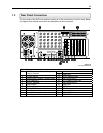
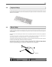
1.3 Rear Panel Connectors
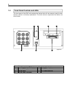
The rear panel of the DVR unit contains virtually all of the connectors you will be using. Below
is a diagram that outlines the location and description of each connector:
----=
Figure 1.3
12 Audio Line In 1 BNC Connector for Camera Input and
Looping Outputs
13 USB Ports
2 75 Ohm Switch 14 RJ-45 Network Jack
3 Control Alarm Outputs / Sensor Inputs 15 DB-9 Serial Input 1
4 RCA Video OUT 16 LPT Parallel Printer Port
5 RS-422 Interface 17 DB-9 Serial Input 2
6 Audio Inputs 18 USB Ports
7 S-Video Output 19 PS/2 Keyboard Input
8 DB-15 SVGA Monitor Output 20 PS/2 Mouse Input
9 DVI-I Output 21 Secondary Power switch
10 Audio Microphone In 22 110V / 220V Switch
11 Audio Speaker Out 23 IEEE AC Power Adapter
Figure 1.3
KV-PCDVR16 Shown