


12
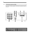
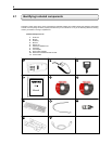
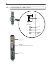
Video Inputs – The Video inputs are RG-59 BNC connectors. Simply plug one end into your video source (DVD,
Camera, etc.) and plug the other end into the desired BNC input on the DVR unit.
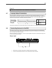
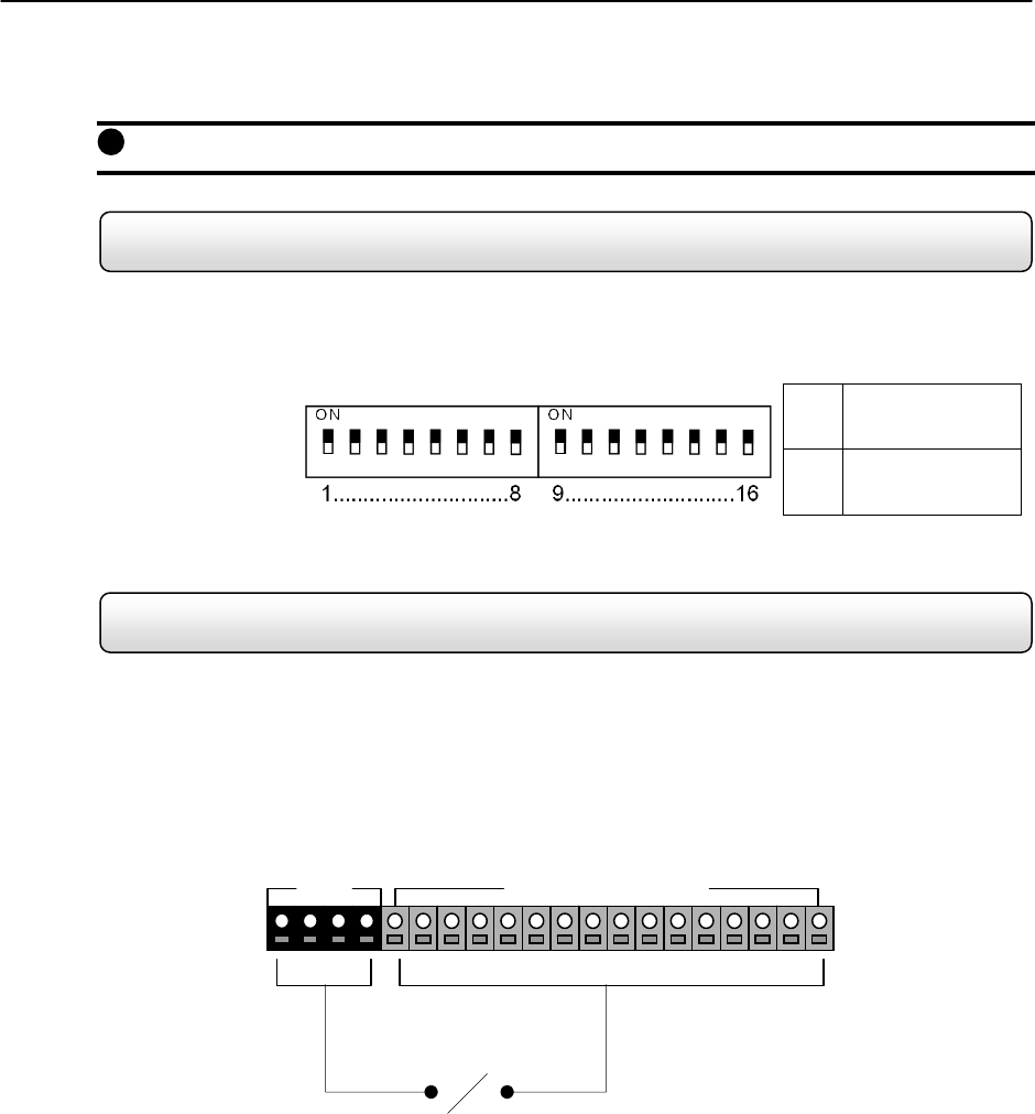
2.7 Looping Output Termination
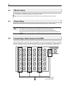
When terminating the outputs becomes necessary, the DVR unit has built-in termination that allows you to select
individual outputs to be terminated. Generally it is not necessary to terminate the output when using it. It is dependant
on if the device to which you are connecting it, has internal 75 ohm termination. As a rule, if the image appears
distorted or virtually unviewable, it most likely needs to be terminated.
ON
Not connected to a
monitor (Normal)
Terminating
the Looping
Outputs
OFF
Connected to a
monitor
(Looped)
Always leave the dipswitch set to the ON position when the Looping Outputs are not used.
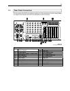
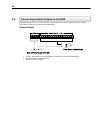
2.8 Connecting Sensors to the DVR
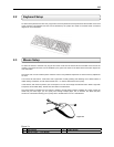
Each DVR unit may have up to 16 Sensor inputs. These inputs can be used with devices such as Infrared devices,
motion devices, glass breakage alarms, door and window trips, and many more. The Sensors can be set to Normally
Open or Normally Closed inside the software.
There are 4 Commons (-) and 16 inputs (+). There is no power supplied to the ports so an external power supply must
be used if power becomes necessary.
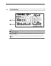
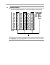
Sensor Input
• Normally Open or Normally Closed option is available inside the DVR Software.
• There is no power supplied to the ports. Use an external power supply if necessary.
Fi
g
ure 2.6
1
COM Sensor (1 ~ 16)