


18
Chapter 2: Connecting your TV
62HM15
Copyright © 2005 TOSHIBA CORPORATION. All rights reserved.
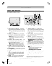
TheaterNet
OUT
IN
AUDIO
AUDIO
IN
S-VIDEO
VIDEO 1 VIDEO 2
OUT 1
INK
INK
DIGITAL
AUDIO OUT
ANT1
CableCARD™
COLOR
STREAM
HD-1
COLOR
STREAM
HD-2
TheaterNet
OUT 2
1
S-VIDEO
IEEE1394
EJECT
L/
MONO
AUDIO
VIDEO
R
L/
MONO
AUDIO
VIDEO
R
P
B
P
R
Y
L
AUDIO
R
TheaterNet
IN from ANT
VIDEO AUDIO
OUT to TV
CH 3
LR
LR
CH 4
IN
OUT
OUT
OUT
IN
Signal splitter
IN from ANT
VIDEO AUDIO
OUT to TV
CH 3
L
R
L
R
LR
CH 4
IN
OUT
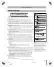
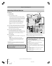
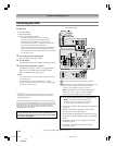
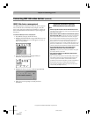
Connecting two VCRs
You will need:
one signal splitter
three coaxial cables
two sets of standard A/V cables
• For better picture performance, if VCR 1 has S-video,
use an S-video cable (plus the audio cables) instead of
the standard video cable. However, do not connect both
types of video cable to VIDEO 1 (or VIDEO 2) at the same time
or the picture performance will be unacceptable.
• If VCR 1 has mono audio, connect L/MONO on the TV (VIDEO 1) to
the audio out terminal on VCR 1 using the white audio cable only.
• Do not connect the same VCR to the output and input terminals on
the TV at the same time.
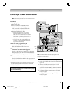
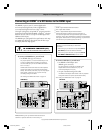
To view the antenna or Cable signal:
Select the ANT-1 video input source.*
To view VCR 1:
Turn ON VCR 1. Select the VIDEO 1 video input source.*
To dub or edit from VCR 1 to VCR 2:
Turn ON both VCRs. Set VCR 2 to the appropriate line
input (refer to your VCR owner’s manual for details).
Select the VIDEO 1 video input source.*
Note:
• If you have a Cable box, connect the Cable box and splitter to VCR1
as shown on page 14.
•The VIDEO OUT signal incorporates Macrovision
®
copyright
protection technology, which may prevent you from recording certain
copy-restricted video materials.**
The VIDEO OUT terminal does not output the POP picture.
When POP mode is active, the AUDIO OUT terminals output the
sound of the active window (main or POP). For additional
information, see “Notes about recording” on page 73.
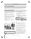
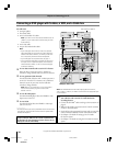
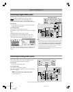
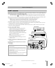
a
VCR1 (plays)
From antenna or Cable
TV
VCR2 (records)
a
The unauthorized recording, use, distribution, or revision of television
programs, videotapes, DVDs, and other materials is prohibited under the
Copyright Laws of the United States and other countries, and may subject
you to civil and criminal liability.
**This product incorporates copyright protection technology that is protected by
U.S. patents and other intellectual property rights. Use of this copyright protection
technology must be authorized by Macrovision and is intended for home and other
limited pay-per-view uses only, unless otherwise authorized by Macrovision.
Reverse engineering or disassembly is prohibited. Macrovision is a registered
trademark of Macrovision Corporation.
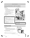
b
b
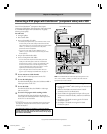
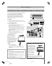
To use the TV Guide On Screen
®
recording features:
Note: If you connect your devices according to the
illustration above, you will record from the TV Guide
On Screen
®
system to the VCR labeled “VCR2.”
1. Connect the G-LINK
®
cable according to the instructions
on page 25.
2. Make sure the VCR2 is connected to the A/V OUT
terminals on the TV (see illustration).
3. Set the VCR to the appropriate line input (refer to your
VCR owner’s manual for details), and then turn OFF the
VCR.
4. See Chapter 5 for details on setting up the TV Guide
On Screen
®
system.
5. See Chapter 7 for details on using the TV Guide
On Screen
®
system.
Note: The VIDEO/AUDIO OUT terminals output the signals
from the ANT 1, ANT 2, VIDEO 1, VIDEO 2, or VIDEO 3
terminals when the appropriate input mode is selected.
_____________
* To select the video input source, press INPUT on the remote control
(see page 66). To program the TV remote control to operate other
devices, see Chapter 3.
#01E012-025_62HM15 5/24/05, 6:17 PM18
Black