11
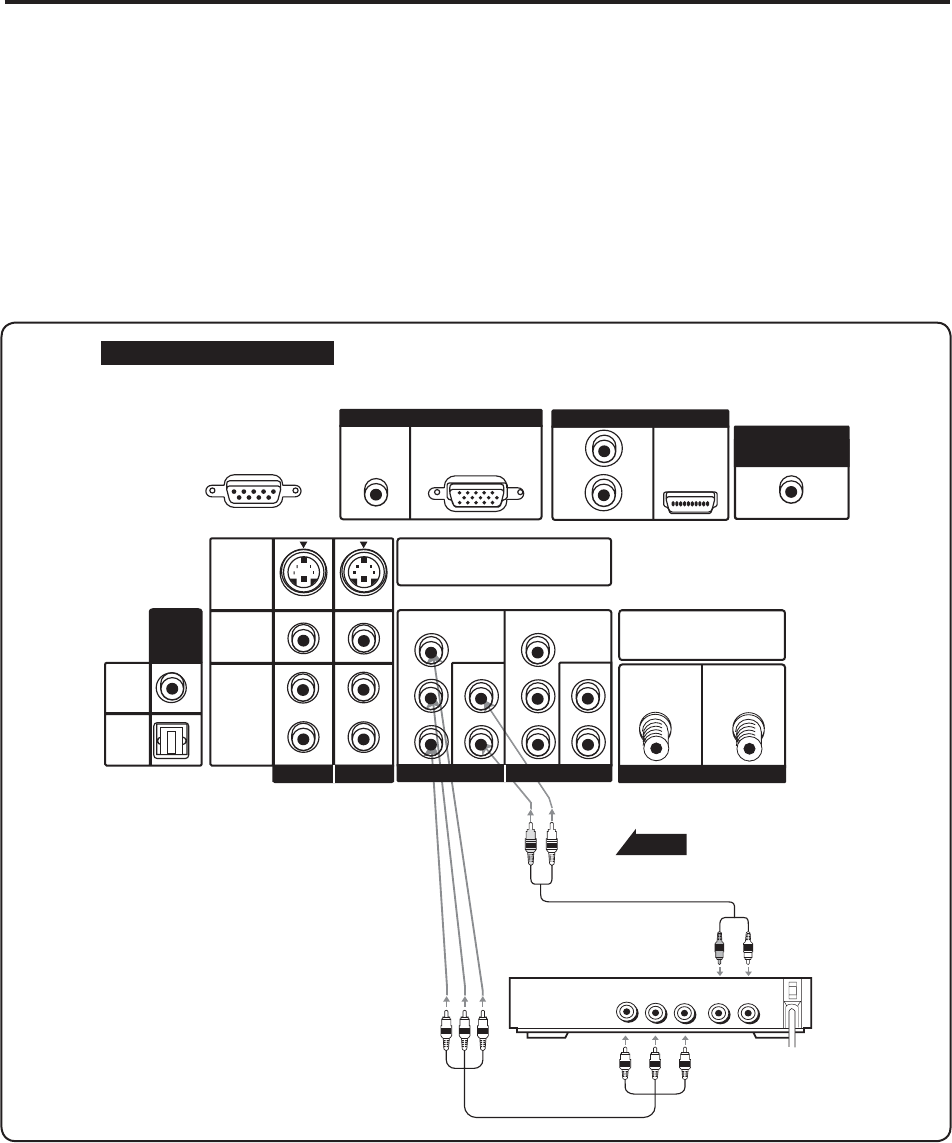
Connecting your DVD Player
Using Component Videoo
1. Turn off the power to the RPTV and DVD player.
2. Connect the PR or CR (red color) connector from the rear of your DVD player to the PR/CR (red color)
connector in the COMPONENT IN 1 on the rear of your RPTV.
3. Connect the PB or CB (blue color) connector from the rear of your DVD player to the PB/CB (blue color)
connector in the COMPONENT IN 1 on the rear of your RPTV.
4. Connect the Y (green color) connector from the rear of your DVD player to the Y (green color) connector in the
COMPONENT IN 1 on the rear of your RPTV.
5. Connect the R (red color) and L (white color) audio connectors from the rear of your DVD player to the R (red
color) and L (white color) audio input connectors in the COMPONENT IN 1 from the rear of your RPTV.
6. Turn on the power of the RPTV and DVD player.
7. Select COMP 1 using the INPUT button on the right side of the RPTV or on the remote control.
Back of Rear Projection TV
Signal
AUDIO
LR
YP
B
P
R
Audio cable
(not supplied)
Component cable
(not supplied)
VIDEO Equipment
Note:
a). If you are already using the Component IN1 input for another component, or you do not want to use the
Component IN1 input for the DVD Player, your can connect the DVD player to the Component IN2 group of
connection.
b). Refer to your DVD player User Manual for more information about the video output requirements of the product.
FORSERVICEONLY
(RS-232C)
EntertheS-VIDEOortheVIDEOterminal
canbeused,buttheS-VIDEOoverrides
theVIDEOterminal.
MakesureANALOG/DIGITALRF
DIGITAL
ANALOG
Inputsareconnectedcorrectly.
AUDIO(L/R)
RGB
L
L
L
R
R
R
AUDIO
S-VIDEO
VIDEO
AUDIO
AUDIO
AUDIO
AUDIO
(ATSConly)
(ATSConly)
OUTPUT
DIGITAL
COAXIAL
OPTICAL
Y
Y
P
B
PB
PR
PR
L
L
R
R
AV IN1AV IN1
AV IN2AV IN2
COMPONENTIN1
COMPONENTIN2
ANTENNAIN
PCINPUTPCINPUT
HDMI
CENTERCHANNELCENTERCHANNEL
INPUT


