Hydraulic Installation 17
MAN0063 (12/15/00)
#46675 Control Valve & #1001420 Hose Kit Cont’d
2
Install #1001421 Adapter Plate from
Hose Kit
■ Before attempting to install this kit, the fol-
lowing must be observed:
1. Shut off engine, place transmission in
neutral, and apply parking brake.
2. Fully lower any equipment supported by
the tractor remote hydraulic valves, if so
equipped. Activate any remote valves to
relieve all hydraulic pressure in the remote
circuits.
3. Fully lower the 3-point hitch.
1. Thoroughly clean the top front of the hydraulic
accessory plate.
2. Remove accessory plate. Be careful not to dis-
turb the O-rings that need to stay with the cover
plate removed.
■ Removal of the accessory plate or remote
valves with a load being held on the 3-point
hitch will result in escape of high pressure oil
and sudden, uncontrolled drop of 3-point hitch
arms.
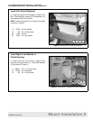
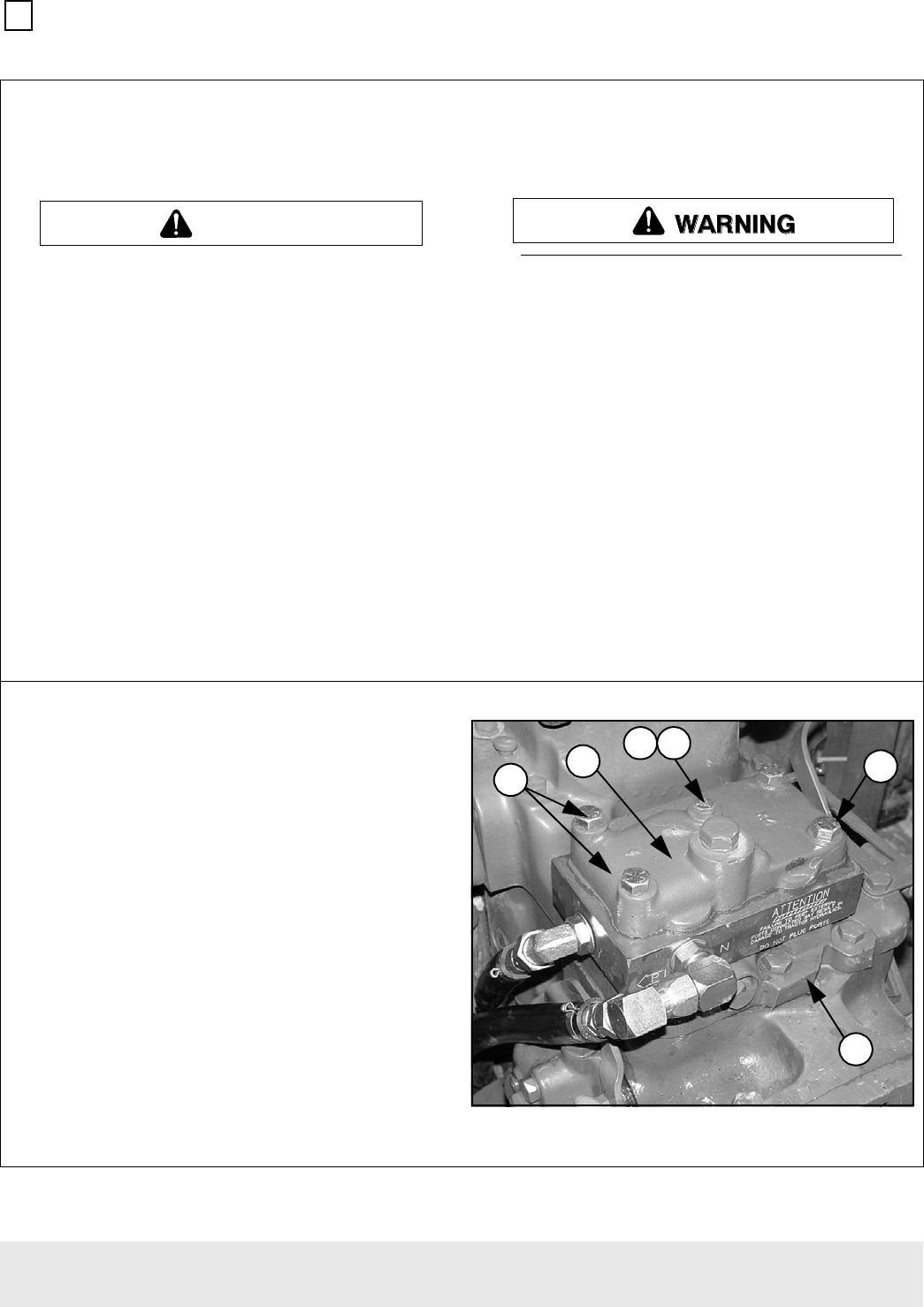
3. Install O-rings into #1001421 PBY adapter
plate. Use petroleum jelly to keep the O-rings in the
counterbores.
4. Place the adapter plate onto the hydraulic lift
cover.
5. Place the accessory plate onto the adapter
plate. Verify that the seal rings stay in the counter-
bores.
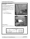
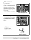
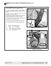
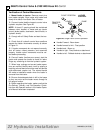
6. Secure with hex head cap screws and flat
washer as shown in Figure 14.
1. 21548 5/16 x 3-1/4 Cap screw
2. 4378 5/16 Standard flat washer
3. 21549 7/16 x 3 Cap screw
4. 1001423 7/16 X 4-3/4 Cap screw
5. ----- Hydraulic accessory plate
6. ----- Hydraulic lift cover
NOTE: This hardware will be used with the stan-
dard accessory plate. If tractor is equipped with an
optional auxiliary quick-coupler valve, obtain hard-
ware locally.
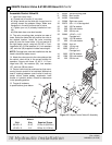
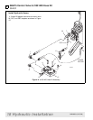
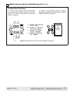
Figure 13 Adapter Plate Installation
(3930 shown)
CAUTION
21
4
5
6
3


