


74-EN
+01GB07IVAD105.fm
ALPINE IVA-D105 68-08564Z59-A (EN)
Installation
Installing the Monitor
Installation Location
Before deciding on the mounting location, check that opening and
closing the display will not hamper gear shifting in that position.
• Install at an angle of within 30 degrees from the horizontal.
• The monitor’s angle is set to 90 degrees at the factory. Depending on
the car, the monitor may hit the dashboard when opened. The
monitor’s angle can be adjusted and stored in memory so that the
monitor will not hit the dashboard when opening. For adjusting the
monitor, refer to “Adjusting the Monitor Angle” on page 39.
Even when the vehicle’s battery power is removed, the adjusted
monitor angle remains stored in memory.
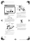
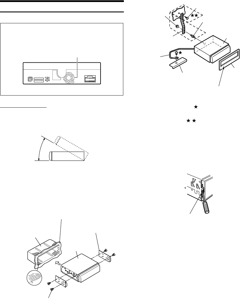
Removal
1. Use a small screwdriver (or similar tool) to push the
locking pins to the “up” position (see Step 3). As each
pin is unlocked, gently pull out on the unit to make sure
it does not re-lock before unlocking the second pin.
2. Pull the unit out, keeping it unlocked as you do so.
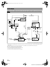
1
Slide the mounting sleeve into the dashboard. Install the
supplied bracket on the monitor.
• Make sure to use the supplied Flush head screw (M4 × 3) to
install the monitor.
If you use another screw to install the monitor, it may cause a
malfunction.
* If the installed mounting sleeve is loose in the dashboard, the
pressure plates may be bent slightly to remedy the problem.
Air ventilation hole
Caution
Do not block the unit’s fan or heat sink, thus preventing
air circulation. If blocked, heat will accumulate inside
the unit and may cause a fire.
Rear of the Unit
Mounting Sleeve
(Included)
Mounting Bracket
(Included)
IVA-D105
Flush head Screws (M4 × 3) (Included)
Dashboard
Pressure Plates*
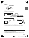
2
Reinforce the monitor unit with a metal mounting strap (not
supplied). Secure the ground lead of the unit to a clean
metal spot using a screw ( ) already attached to the
vehicle’s chassis.
• For the screw marked , use an appropriate screw for the
chosen mounting location.
Connect each input lead coming from an amplifier or
equalizer to the corresponding output lead coming from the
left rear of the IVA-D105. Connect all other leads of the IVA-
D105 according to details described in the Connections
section.
3
Slide the IVA-D105 into the dashboard. When the unit is in
place, make sure the locking pins are fully seated in the
down position. This can be done by pressing firmly in on the
unit while pushing the locking pin down with a small
screwdriver. This ensures that the unit is properly locked
and will not accidentally come out from the dashboard.
Install the supplied Front Frame.
Screw
Bolt Stud
IVA-D105
Front Frame
(Included)
Wider edge should face down.
Chassis
Ground
Lead
Meatal Mounting
Strap
Hex Nut (M5)
Lock Pin
+01GB00IVAD105.book Page 74 Monday, January 15, 2007 4:02 AM