


13
MODEL TCL SECTION 4
WIRING
SECTION 4. WIRING
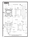
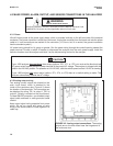
4.1 PREPARE ANALYZER CONDUIT OPENINGS
The analyzer enclosure has six conduit openings. Four conduit openings are fitted with conduit plugs.
Conduit openings accept 1/2-inch conduit fittings or PG 13.5 cable glands. To keep the case watertight, block
unused openings with NEMA 4X or IP65 conduit plugs.
NOTE
Use watertight fittings and hubs that comply with the requirements of UL514B. Connect the conduit hub to the
conduit before attaching the fitting to the analyzer (UL508-26.16).
4.2 PROVIDE POWER TO THE SAMPLE CONDITIONING SYSTEM
NOTE
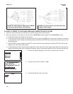
1. Be sure the pump switches on the wiring access panel are in the off position.
2. Remove the four screws securing the wiring access panel. Pull the panel out of the way to reveal the power
terminal strip.
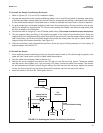
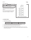
3. Insert the power cable through the strain relief connection labeled power (see Figure 3-4). Wire the power
cable to the terminal strip as shown in Figure 4-1. Do not apply 230 Vac power to a 115 Vac TCL (Model option
-11). Doing so will damage the instrument.
4. Leave the pump power switches off until ready to start up the unit. See Section 5.
FIGURE 4-1. Power Wiring
Model option -11 115 Vac only
Model option -12 230 Vac only
Electrical installation must be in accordance with the National Electrical Code
(ANSI/NFPA-70) and/or any other applicable national or local code.
WARNING
RISK OF ELECTRICAL SHOCK
Provide a switch or breaker to disconnect the sample conditioning cabinet from the
main power supply. Install the switch or breaker near the unit and identify if as the
disconnecting device for the sample conditioning system.