


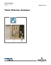


MODEL TCL TABLE OF CONTENTS
LIST OF FIGURES
Number Title Page
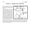
2-1 Schematic of Sample Conditioning System and Analyzer .................................... 7
3-1 Panel Mount Dimensions ....................................................................................... 9
3-2 Pipe and Wall Mounting Dimensions ...................................................................... 10
3-3 Installing the Sample Conditioning Enclosure......................................................... 11
3-4 TCL Case Dimensions ............................................................................................ 12
3-5 Reagent Tubing Assembly ...................................................................................... 12
4-1 Power Wiring .......................................................................................................... 13
4-2 Location of power connector on power supply board. ............................................ 14
4-3 Analog output connections...................................................................................... 15
4-4 Wiring Sensor with Optimum EMI/RFI or Variopol Cable to Model 1056 Analyzer.... 16
4-5 Wiring Sensor with Standard Cable to Model 1056 Analyzer.................................. 16
6-1 Main Display .......................................................................................................... 20
6-2 Programming Screen Showing Item List................................................................. 20
6-3 Arrow Bar............................................................................................................................................ 20
6-4 Analyzer keypad .................................................................................................... 21
6-5 Navigation keys....................................................................................................... 21
7-1 High Alarm Logic .................................................................................................... 33
7-2 Low Alarm Logic...................................................................................................... 33
7-3 Operation of the interval timer................................................................................. 33
9-1 Determination of Total Chlorine .............................................................................. 44
9-2 Sensor Current as a Function of Total Chlorine Concentration .............................. 44
10-1 Sensor Board Connections .................................................................................... 49
10-2 Sensor Parts ........................................................................................................... 51
10-3 Replacing Reagent Tubing...................................................................................... 52
10-4 Replacing Sample Tubing....................................................................................... 53
10-5 Peristaltic Pump Tubing .......................................................................................... 54
10-6 Pump Cover............................................................................................................ 54
10-7 Removing the Cover............................................................................................... 54
10-8 Inserting New Tube................................................................................................. 54
10-9 Replace the Cover.................................................................................................. 55
10-10 Bottom of the Cover................................................................................................ 55
10-11 Tracks .....................................................................................................................55
10-12 Disconnection ......................................................................................................... 56
10-13 Removal of Screws................................................................................................. 56
10-14 Connect the Air Inlet and Outlet Tubing to the Air Pump......................................... 56
10-15 Schematic ............................................................................................................... 56
10-16 Remove the Air Inlet Fitting..................................................................................... 57
10-17 Slide Pump Assembly Out of the Airp Pump Body.................................................. 57
iii