


REAR PANEL CONNECTIONS 15
ENGLISH
B
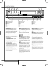
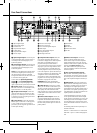
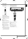
Zone 1 Analog Audio Outputs: If you are
not using either HDMI or a separate optical or
coaxial digital audio connection for the Zone 1
(Main Room) audio, connect these jacks to the
matching inputs on your A/V receiver or sur-
round processor. Connect the left- and right-
channel jacks to the receiver to monitor an ana-
log source connected to the Auxiliary Inputs dur-
ing recording.
Note: You’ll find more details about all
Audio/Video connections under Setup and
Connections on the following pages.
C
Analog Audio Inputs: Connect these jacks
to an audio output on a source player like a tape
deck or record player for analog audio recording.
D
The Bridge Connection: To use an iPod*
as a source for the DMC 1000, enabling you to
select and listen to audio content and charge
the iPod, connect an optional Harman Kardon
The Bridge here.
*For iPod models with a dock connector.
E
Network Jack: Connect this standard RJ45
jack to a broadband network (Ethernet) connec-
tion so that you may take full advantage of
Gracenote MusicID, including obtaining cover art
for stored albums, updating both the database
of album information and the system software,
and connecting the DMC 1000 to a home net-
work. When the network connection is “live,”
the lights on either side of the jack will flash to
indicate network activity.
F
USB Port: This USB port is primarily intend-
ed to connect an optional, external USB hard
drive to back up the DMC 1000’s Media Library,
although it may be used for content playback.
DO NOT connect a computer or other host
device directly to the DMC 1000.
G
RS-232 Port: Connect the DMC 1000 to
compatible system control and automation prod-
ucts, using a standard RS-232 cable. As pro-
gramming a control and automation system is a
complex task, requiring specific information and
training, we recommend that you consult a
trained installer.
H
Master Power Switch: Push this switch
to the line position (I) to apply power to the
DMC 1000, placing it in the “Full-Off” power
mode. When the unit will not be used for an
extended period of time, or whenever it is neces-
sary to remove the unit from the AC power lines,
push the switch to the circle position (0) to turn
the unit off.
I
Fan Vent: This area contains vents used by
the DMC 1000’s fans to cool the system.
Maintain a clearance of at least three inches to
the nearest surface, to avoid overheating the
unit.
2083124_HK_DMC_1000_OM_ENG.qxp:34241_DMC250_ENG 15/08/08 10:49 Side 15