*
1. ASSEMBLED P.W.B. ADJUSTMENT
1 .l Memory Initialization
Adjustment procedure
(1) Press INPUT key on Control Panel and then
Power On to access Video Chroma adjustment
mode.
(2) Receive signal on main picture.
(3) Check the OSD according to table below, using
Av buttons on Remote Control.
P.01 AP84
SERVICE
0
SUB CONT 14
SUB COLOR 10
SUB TINT
45
SUB SHARP 38
EXT RGB BRIGHT 40
EXT RGB CONT 60
BRIGHTNESS 80
SUB BRIGHT ADJ. 0
INITIAL SET 0
PO2
G DRIVE GAIN
B DRIVE GAIN
H POSITION
AFC G
H BLK END PHASE
V BLK PHASE
V FREQUENCY
V POSITION
R-Y POSITION
R-Y LEVEL
G-Y LEVEL
GPPHS
P.03
S-TRAC
YA
Y DL
TXACL
COLOR A
AP84
1
n
0
1
i-l
C TRAP
0
TOF FQ
0
TOF Q
0
COLOR SYSTEM
0
DY GAIN
9
B.E. P POINT1
P.05 1 AP84
WPDL 1 1
I
HI BRT
! 1 I
I-l+1
B CUT OFF 80
P.06 AP84-
H POSI (CENT)
04 *
I
V POSI (CENT) 1 07 I*
I
INITIAL SET
1 0
Z OSD SETTINGS
I
CLAMP DELAY
*: Adjustable data.
Others: Fixed data (be careful not to change)
(4) Check MENU key to exit VIDEO CHROMA
ADJUST mode.
NOTE: (1) If there is a different value than shown
in table above, for fixed data, adjust it
using 4, buttons (only in this case).
(2) When exchanging microprocessor and
TV is turned on for first time, it requires
initialization of VIDEO CHROMA ADJ
on Pl and P6.
(3) Should be changed to OFF for FIRST
TIME TOUR at first Power ON by
pressing MENU key during FIRSTTIME
TOUR running.
24
1.2 Comb filter operation check
Adjustment preparation
(1) Receive the color bar signal at the regular tuning
point.
(2) Set the CONTRAST control to MAX and the
other controls to center.
(3) Set the Al to OFF, and 3D Y/C to ON in
Advanced Settings.
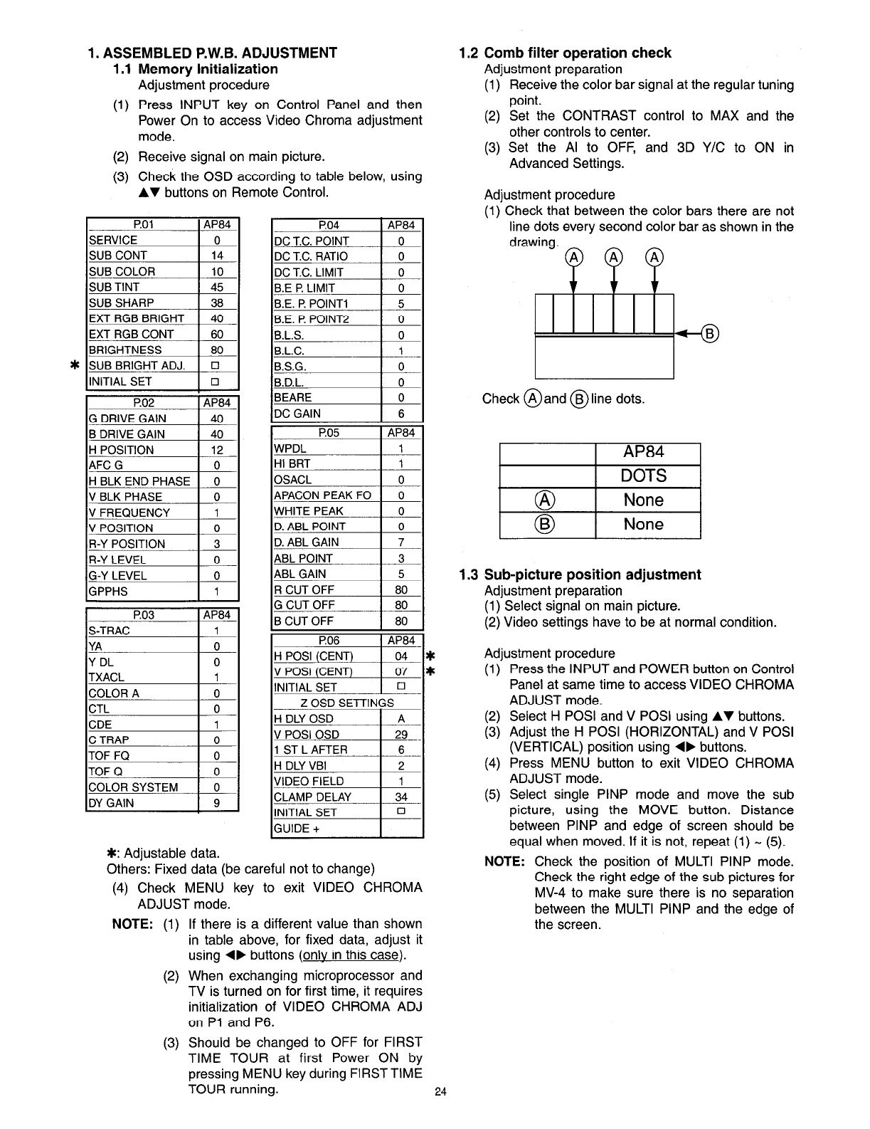
Adjustment procedure
(1) Check that between the color bars there are not
line dots every second color bar as shown in the
1.3
drawing.
Check @and (@line dots.
Sub-picture position adjustment
Adjustment preparation
(1) Select signal on main picture.
(2) Video settings have to be at normal condition.
Adjustment procedure
(1)
;:;
(4)
(5)
Press the INPUT and POWER button on Control
Panel at same time to access VIDEO CHROMA
ADJUST mode.
Select H POSI and V POSI using A’(I buttons.
Adjust the H POSI (HORIZONTAL) and V POSI
(VERTICAL) position using 4, buttons.
Press MENU button to exit VIDEO CHROMA
ADJUST mode.
Select single PINP mode and move the sub
picture, using the MOVE button. Distance
between PINP and edge of screen should be
equal when moved. If it is not, repeat (1) - (5).
NOTE: Check the position of MULTI PINP mode.
Check the right edge of the sub pictures for
MV-4 to make sure there is no separation
between the MULTI PINP and the edge of
the screen.


