


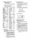
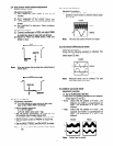
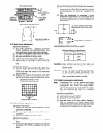
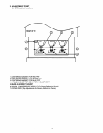
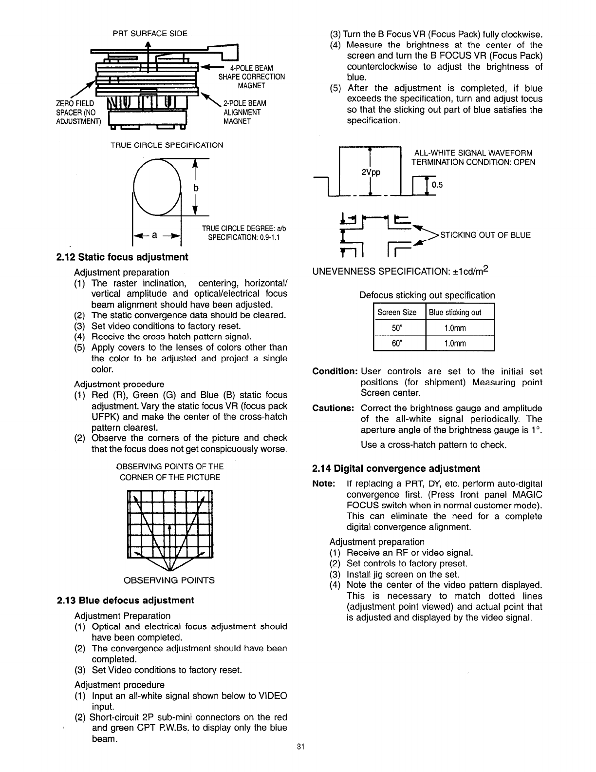
PRT SURFACE SIDE
1 e 4-POLE BEAM
SHAPE CORRECTION
MAGNET
2-POLE BEAM
ALIGNMENT
TRUE CIRCLE SPECIFICATION
MAGNET
TRUE CIRCLE DEGREE: a/b
SPECIFICATION: 0.9-l .l
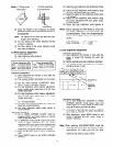
2.12 Static focus adjustment
Adjustment preparation
(1)
(2)
I:;
(5)
The raster inclination, centering, horizontal/
vertical amplitude and optical/electrical focus
beam alignment should have been adjusted.
The static convergence data should be cleared.
Set video conditions to factory reset.
Receive the cross-hatch pattern signal.
Apply covers to the lenses of colors other than
the color to be adjusted and project a single
color.
Adjustment procedure
(1)
(2)
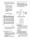
Red (R), Green (G) and Blue (B) static focus
adjustment. Vary the static focus VR (focus pack
UFPK) and make the center of the cross-hatch
pattern clearest.
Observe the corners of the picture and check
that the focus does not get conspicuously worse.
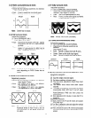
OBSERVING POINTS OF THE
CORNER OF THE PICTURE
OBSERVING POINTS
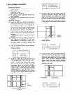
2.13 Blue defocus adjustment
Adjustment Preparation
(1) Optical and electrical focus adjustment should
have been completed.
(2) The convergence adjustment should have been
completed.
(3) Set Video conditions to factory reset.
Adjustment procedure
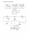
(1) Input an ail-white signal shown below to VIDEO
input.
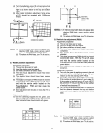
(2) Short-circuit 2P sub-mini connectors on the red
and green CPT P.W.Bs. to display only the blue
beam.
(3) Turn the B Focus VR (Focus Pack) fully clockwise.
(4) Measure the brightness at the center of the
screen and turn the B FOCUS VR (Focus Pack)
counterclockwise to adjust the brightness of
blue.
(5) After the adjustment is completed, if blue
exceeds the specification, turn and adjust focus
so that the sticking out part of blue satisfies the
specification.
1
ALL-WHITE SIGNAL WAVEFORM
TERMINATION CONDITION: OPEN
STICKING OUT OF BLUE
UNEVENNESS SPECIFICATION: +1cd/m2
Defocus sticking out specification
60”
1 .Omm
Condition: User controls are set to the initial set
positions (for shipment) Measuring point
Screen center.
Cautions: Correct the brightness gauge and amplitude
of the all-white signal periodically. The
aperture angle of the brightness gauge is lo.
Use a cross-hatch pattern to check.
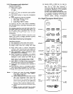
2.14 Digital convergence adjustment
Note: If replacing a PRT, DY, etc. perform auto-digital
convergence first. (Press front panel MAGIC
FOCUS switch when in normal customer mode).
This can eliminate the need for a complete
digital convergence alignment.
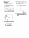
Adjustment preparation
;:;
(3)
(4)
Receive an RF or video signal.
Set controls to factory preset.
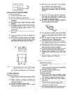
Install jig screen on the set.
Note the center of the video pattern displayed.
This is necessary to match dotted lines
(adjustment point viewed) and actual point that
is adjusted and displayed by the video signal.
31