


(5)
(6)
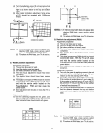
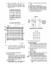
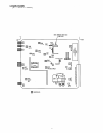
Press the service only switch
(on
POWER/DEFLECTION PWB). The pattern
displayed is now the digital convergence mode.
When performing a complete
digital
convergence adjustment CLEAR DATA in RAM.
See 2.6. (1) - (7).
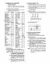
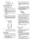
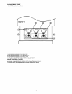
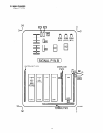
Adjustment Point
JIG SCREEN SPECIFICATION
GEOMETRIC CENTER OF THE SCREEN
(84.9) [102.1]
[1227.2]
ki
a
MODEL: (50”), [60”]
UNIT: mm
Note: If only minor adjustments to convergence are
needed, the jig screen is not necessary. Use
digital data stored in memory and one color as a
reference (red, green, or blue). DO NOT CLEAR
DATA and WRITE to ROM memory.
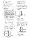
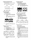
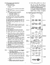
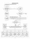
2.14.1 Phase adjustment (service mode)
Adjustment preparation
(1) PHASE adjustment - This is to match the digital
convergence cursor position to the video image
displayed, and to match the digital convergence
cursor position (dotted lines) to digital
convergence data position (bent lines).
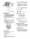
Adjustment procedure
(1) Press the HELP button on the remote to select
phase adjustment. (Only Green displayed).
(2)
I:;
(5)
(6)
(7)
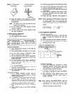
Identify the bent lines and use the cursor
buttons to move the dotted lines in between as
shown.
Press HELP to exit PHASE mode.
Press ENTER 5 times to display external signal.
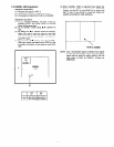
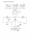
Identify center of active video, then press
ENTER 5 times to return to internal cross-hatch.
Press HELP (phase adj.), and use 2, 4, 5 and 6
to position internal cross-hatch center on active
video center identified in step (5).
Press HELP to exit PHASE mode.
ACTIVE
VIDEO
CENTER
FROM
STEP (5)
BEFORE
USE CURSOR
KEYS TO MOVE
DOTTED LINES
3ElWEEN BENT
LINES FIRST
THEN USE NUMBER KEYS TO MATCH INTERNAL
CROSSHATCH CENTER TO ACTIVE VIDEO CENTER
AFTER
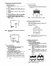
2.14.2 Raster position adjustment
Adjustment preparation
(1) Position adjustment - This will move an entire
color. Use this adjustment to match colors at the
center of the screen. (Active video center from
external signal and physical screen center
should now match from phase adj. 2.15.1.).
(2) Use the buttons below to switch color to adjust.
“RECALL’ - Green
“0” - Red
“INPUT” - Blue
Adjustment procedure
(1) Press the FRZ button. Extra horizontal lines
appear to confirm raster position mode.
(2) Use the cursor buttons to adjust position.
(3) Press FRZ again to exit raster position mode.
Notes:
(1) Other functions cannot be accessed when
in raster position adjustment mode. Press
FRZ and confirm extra horizontal lines
disappear to exit raster position mode.
(2) Press MENU to switch between all colors
displayed or adjustment color and Green
only.