


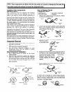
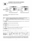
Fuses and Conventional Resistor Removal/Replacement
1. Clip each fuse or resistor lead at top of circuit board
hollow stake.
2. Securely crimp leads of replacement component around
stake l/8 inch from top.
3. Solder the connections.
CAUTION: Maintain original spacing between the
replaced
component and adjacent
components and the circuit board, to
prevent
excessive component
temperatures.
Circuit Board Foil Repair
Excessive heat applied to the copper foil of any printed
circuit board will weaker. the cdhesive that bonds the foil to
the circuit board, causing the foil to separate from, or “lift-off:’
the board. The following guidelines and procedures should
be followed whenever this condition is encountered.
In Critical Copper Pattern Areas
High component/copper pattern density and/or special
voltage/current characteristics make the spacing and
integrity of copper pattern in some circuit board areas more
critical than in others. The circuit foil in these areas is
designated as Critical Copper Pattern. Because Critical
Copper Pattern requires special soldering techniques to
ensure the maintenance of reliability and safety standards,
contact your Hitachi personnel.
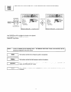
At IC Connections
To repair defective copper pattern at IC connections, use the
following procedure to install a jumper wire on the copper
pattern side of the circuit board. (Use this technique only on
IC connections.)
1. Carefully remove the damaged copper pattern with a
sharp knife. (Remove only as much copper as absolutely
necessary.)
2. Carefully scratch away the solder resist and acrylic
coating (if used) from the end of the remaining copper
pattern.
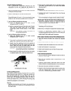
BARE JUMPER
Install Jumper Wire and Solder
3. Bend a small “U” in one end of a small-gauge jumper wire
and carefully crimp i! around the IC pin. Solder the IC
connection.
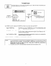
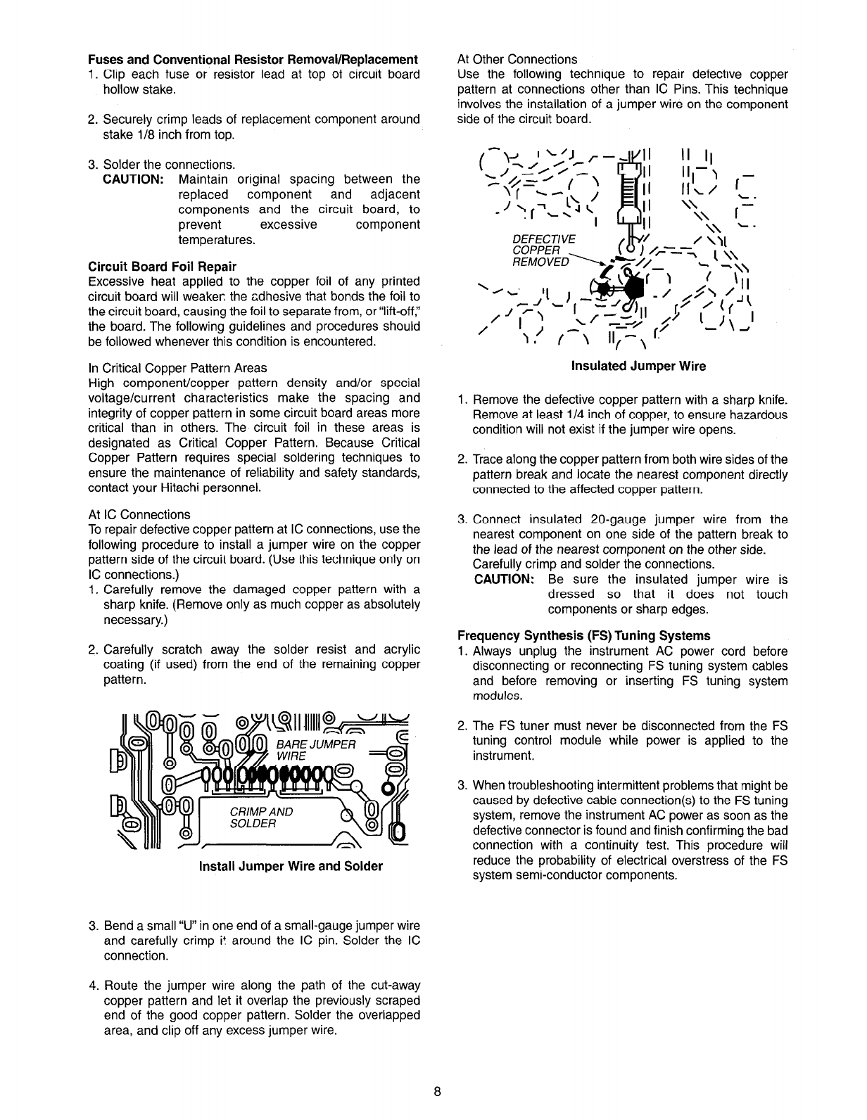
At Other Connections
Use the following technique to repair defective copper
pattern at connections other than IC Pins. This technique
involves the installation of a jumper wire on the component
side of the circuit board.
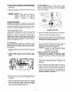
DEfECTlVE
Insulated Jumper Wire
Remove the defective copper pattern with a sharp knife.
Remove at least l/4 inch of copper, to ensure hazardous
condition will not exist if the jumper wire opens.
Trace along the copper pattern from both wire sides of the
pattern break and locate the nearest component directly
connected to the affected copper pattern.
Connect insulated 20-gauge jumper wire from the
nearest component on one side of the pattern break to
the lead of the nearest component on the other side.
Carefully crimp and solder the connections.
CAUTION: Be sure the insulated jumper wire is
dressed so that it does not touch
components or sharp edges.
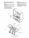
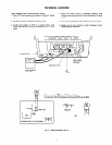
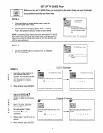
Frequency Synthesis (FS) Tuning Systems
Always unplug the instrument AC power cord before
disconnecting or reconnecting FS tuning system cables
and before removing or inserting FS tuning system
modules.
The FS tuner must never be disconnected from the FS
tuning control module while power is applied to the
instrument.
When troubleshooting intermittent problems that might be
caused by defective cable connection(s) to the FS tuning
system, remove the instrument AC power as soon as the
defective connector is found and finish confirming the bad
connection with a continuity test. This procedure will
reduce the probability of electrical overstress of the FS
system semi-conductor components.
4. Route the jumper wire along the path of the cut-away
copper pattern and let it overlap the previously scraped
end of the good copper pattern. Solder the overlapped
area, and clip off any excess jumper wire.