


10
3 CONNECTIONS (contd.)
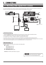
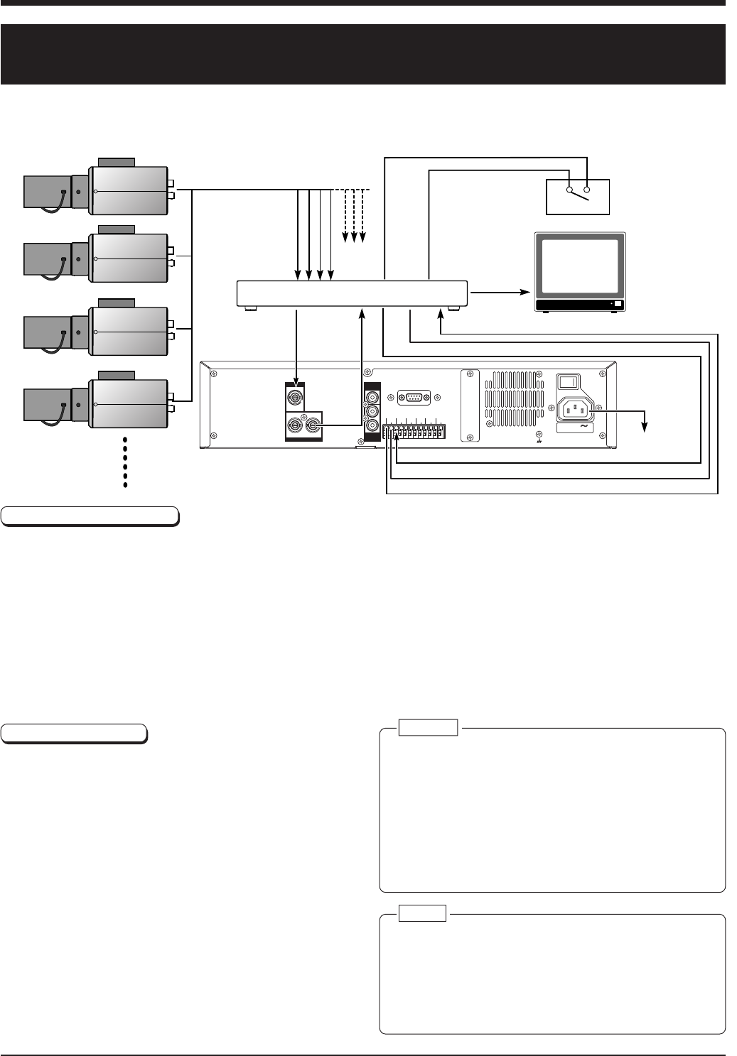
3-2 Connecting more than one camera (using an external
switcher)
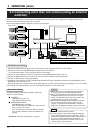
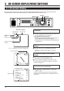
When an external switcher is connected to the [CAMERA IN] connector of this unit, images from multiple cameras can be
recorded. Select the camera image with the switcher.
● For a connectable multiplexer (switcher), consult your JVC dealer.
Connection procedures
1.Connect the video output connector of the frame switcher to the video input connector of the monitor.
2.Connect the camera to the [CAMERA IN] connector of the frame switcher.
* For camera connections, refer to the frame switcher’s instructions.
3.Connect the frame switcher’s [VTR OUT] connector to the [CAMERA IN] connector of this unit.
4.Connect the [MONITOR OUT] connector of this unit to the frame switcher’s [VTR IN] connector.
5.Connect the alarm sensor to the frame switcher.
6.Connect the frame switcher’s [VTR TRIGGER] and [ALARM OUT] signal input/output terminals to the [CAM SW OUT] and
[ALARM IN 1] terminals of this unit.
7.After all connections are complete, connect the power cable to the [AC IN] socket and connect the plug to an AC 120 V outlet.
8.Turn ON all connected equipment, then turn the [POWER] switch on the rear panel to ON.
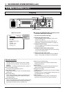
Caution:
● Before connecting or disconnecting any equipment,
turn the power of all connected equipment OFF.
● When a field switcher is used, picture quality will be
degraded if [REC QUALITY] is set to "H". In some
cases, the specified camera may not be used or the
playback picture may move up and down.
● As the camera switching signal is recorded, the picture
on the lower section of the monitor screen may be
missing. To record the external switcher’s on-screen
display, set the display to the upper section of the screen.
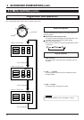
Memo:
● Select the camera with the switcher.
● The monitor picture may not be switched during jog/
shuttle operation and skip search operation. This is
because the playback camera number is different from
the camera number selected with the switcher. To
display the picture from the selected camera on the
monitor, press the [PLAY] button.
CAMERA IN
MONITOR OUT
1
1
2
12
AUDIO
IN
AUDIO
OUT
RS-232C
POWER
SIGNAL GND
CAM SW
OUT
ALARM
IN1
SPARESPARE
SPARE
HDD
FULL OUT
ALARM
RESET
CLOCK
RESET IN
CLOCK
RESET OUT
EXT
REC IN
COM COM
ON OFF
I
O
AC IN 120 V
50 Hz / 60 Hz
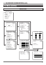
Example of settings when alarm recording is performed
using an external switcher.
Ⅵ DVR MODE
[REC QUALITY] set to “N”
[EXT SWITCHER] set to “ON”
Ⅵ ALARM/SENSOR MODE
[REC MODE] set to “ALARM”
[REC DURATION] set to “MANUAL” when the alarm
time is set with the switcher
This unit continues recording for about 5 seconds
after the alarm duration set with the switcher has
passed.
Reference: “5-3 Menu switch details” on page 19.
Menu switch setting
Video camera
Video camera
Video camera
Video camera
Switcher
To AC 120 V,
50 Hz/60 Hz
Provided
power cable
Monitor
Alarm sensor
ALARM IN
VTR TRIGGER IN
CAM SW OUT
ALARM OUT
COM
COM
COM
ALARM IN
VTR IN
VTR OUT