


7
2 CONTROLS, CONNECTIONS AND DISPLAY (contd.)
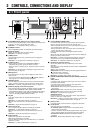
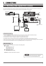
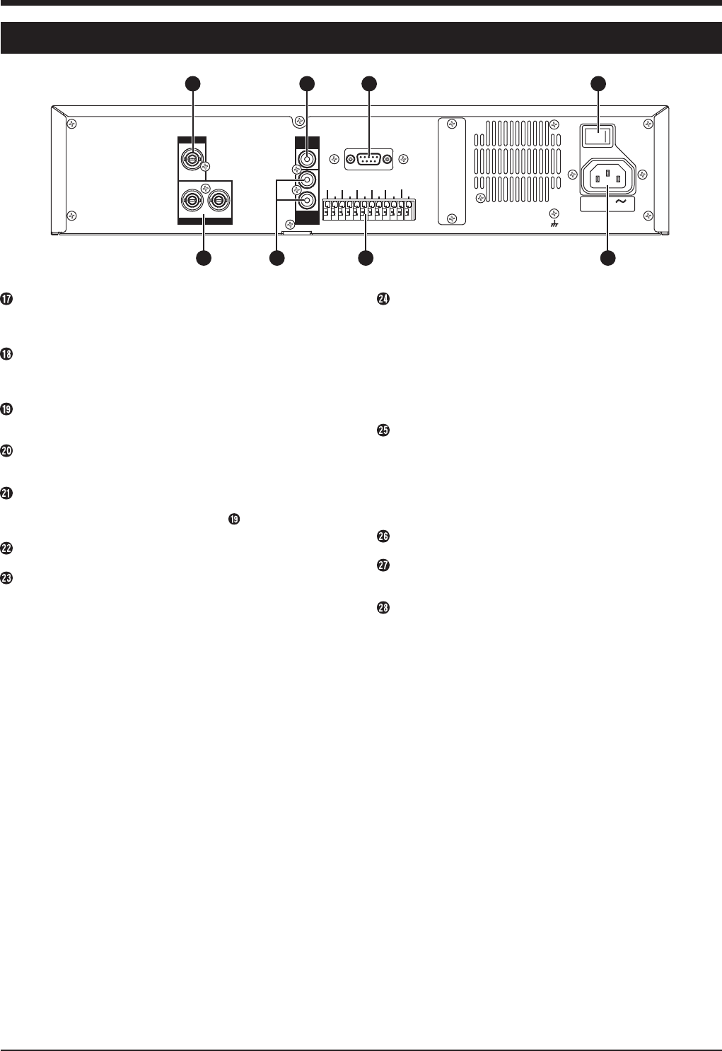
2-2 Rear panel
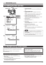
[STOP] button
Press this button to stop operation. In the Simultaneous
Playback mode, press this button to stop playback and engage
the normal recording mode.
[REC] button
Press in the Stop mode to start recording. The recording mode
can be set with the menu switch.
Reference: “6-1 Basic operation” on page 22.
[SLEEP] button
Before turning the power OFF, press this button to stop the
rotation of the hard disk.
[SYSTEM RESET] button
This button is used for servicing. Normally, you do not need to
use this button.
[POWER] switch
Turns power ON/OFF.
*Before turning the power OFF, press the [SLEEP] button to
stop the rotation of the hard disk.
[AC IN] socket
Connect to an AC 120 V outlet using the provided power cable.
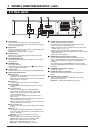
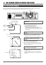
Signal input/output terminal
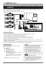
Ⅵ CAM SW OUT
Outputs camera switch timing control signals when this unit is
connected to a frame switcher.
Reference: "3-2 Connecting more than one camera (using an
external switcher)" on page 10.
Ⅵ ALARM IN 1
Accepts signals to start alarm or sensor recording.
Ⅵ ALARM RESET
Accepts signals to stop recording during alarm or sensor
recording.
Ⅵ CLOCK RESET IN
Connect to a master clock or the [CLOCK RESET
OUT] terminal of another device. When a clock reset
signal is input, this unit can be set to the master clock
or the other device’s clock.
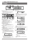
When the clock reset signal is input, the clock second
value is reset: .
●With 29 seconds or less, the minute value stays the same
and the second value is reset to 00.
●With 30 seconds or more, the minute value is increased by 1
and the second value is reset to 00.
Ⅵ CLOCK RESET OUT
Outputs a clock reset signal when the internal clock is 00:00
or 12:00.
Ⅵ EXT REC IN
Recording is automatically activated by an external signal
when menu switch <REC MODE> of <EXT MODE> is set to
“TRIG” or “MANUAL”.
Reference: “5-3 Menu switch details” on page 20.
Ⅵ HDD FULL OUT
Outputs a signal during recording when the hard disk’s
available space is 0% except in the following cases.
●Menu switch <HDD FULL OUT> set to “OFF”
●Menu switch <REPEAT REC> set to “ALL”
Reference: “5-3 Menu switch details” on page 20.
[AUDIO OUT] audio output connector
Outputs recorded audio during playback.
In the Record or Stop mode, outputs the input audio signal.
Audio is not output in the following cases.
● When playing back signals recorded with menu switch <REC
SPEED> set to “1/5” or “1/10”
● In the Frame-by-Frame Playback, Still or Search mode
● When playing back signals recorded with menu switch <AUDIO
REC> set to “OFF”
● When the menu is displayed
[MONITOR OUT] monitor output connector
Outputs video signals recorded on the hard disk in the Play
mode. In the Record mode, outputs video input signals from the
camera or frame switcher connected to the [CAMERA IN]
connector.
The picture signal from the [CAMERA IN] connector is output
through the [MONITOR OUT] connector even when the power is
turned OFF.
[CAMERA IN] camera input connector
Connect to a camera.
[AUDIO IN] audio input connector
Connect to the audio output connector of the audio source
device.
[RS-232C] remote connector
Connect a personal computer or compatible control unit for
external remote operation.
Reference: “10. RS-232C INTERFACE” on page 40.
CAMERA IN
MONITOR OUT
1
1
2
12
AUDIO
IN
AUDIO
OUT
RS-232C
POWER
SIGNAL GND
CAM SW
OUT
ALARM
IN1
SPARE SPARE
SPARE
HDD
FULL OUT
ALARM
RESET
CLOCK
RESET IN
CLOCK
RESET OUT
EXT
REC IN
COM COM
ON OFF
I
O
AC IN 120 V
50 Hz / 60 Hz
26
27
28
21
222325 24