


21
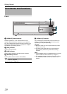
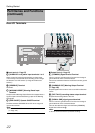
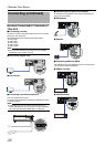
Rear Panel
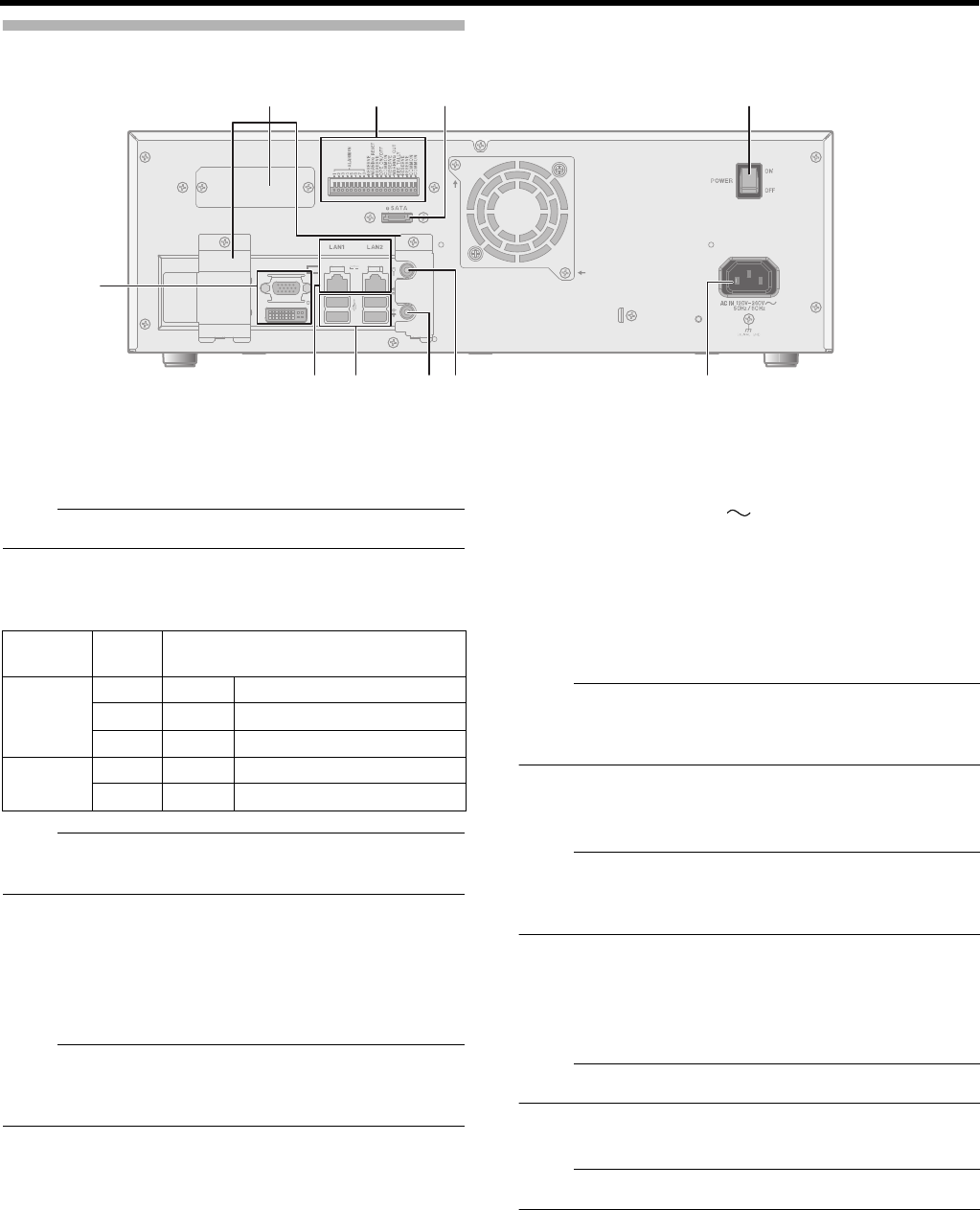
F Monitor Output Terminals (D-sub 15pin, DVI)
Outputs the recorded images, live images or the setup
screen.
Note:
● The DVI terminal emits only digital signals.
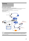
G LAN1/LAN2 Terminals
Connect to the network using a LAN cable.
Note:
● For how to use LAN1/LAN2, refer to “Proper Use of LAN1/
LAN2” (A Page 119).
H SERIAL Terminal
For connecting the communication control terminals on a
USB mouse (sold separately), USB flash memory (sold
separately), UPS (sold separately) or additional HDD (sold
separately).
Note:
● For connection of external devices, consult your nearest
JVC KENWOOD dealer. You can also check on our
website.
I Audio Output Terminal
Connect to an audio output device such as a speaker.
J Audio Input Terminal
Connect to an audio input device such as a plug-in
microphone.
K [AC IN 120V - 240V 50Hz/60Hz] power input
terminal
Connect to an AC120 V to AC240 V outlet using the power
cable supplied.
L [POWER] switch
Switches the power on or off.
Note:
● Be sure to press and hold down the [OPERATE] button on
the front panel to shut down the system before switching
off the power supply.
M [eSATA] Terminal
Connect to an additional HDD (sold separately).
Note:
● For details on additional HDDs you can connect to this
unit, consult your nearest JVC KENWOOD dealer. You
can also check on our website.
N Signal input/output terminals
For operating the unit using external alarm signals or signals
received from external devices, or for operating external
devices by outputting signals.
Note:
● Diameter of applicable cable: AWG22 to AWG28
O Connector cover
Note:
● Do not remove the cover.
NNMM LL
KKJJIIHH
F
GG
OO
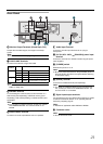
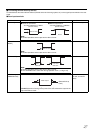
Indicator
position
Color Status
Left - Off Communication at 10 Mbit/s.
Green On Communication at 100 Mbit/s.
Orange On Communication at 1 Gbit/s.
Right - Off Not connecting to the network.
Yellow Blinking Communication is in progress.