


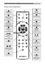
Control Elements, Displays and Connections
8
Control Elements, Displays and Connections
This section contains a brief description of all the control elements,
displays and connections. The key symbols presented here are also
used when describing operating sequences.
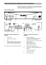
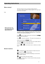
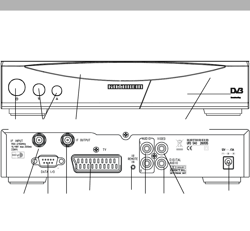
View of front panel
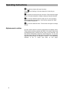
View of rear panel
Front panel control elements and
displays
Rear panel control elements and
displays
1 On/Off switch
2 Channel buttons (up/down)
3 LED
4 Common Interface for Pay-TV cards*
)
– be-
hind front flap, open by lightly applying
pressure on the upper right-hand corner
_________________________________________
*
)
CA module and Pay-TV cards are not included in delivery
1 Satellite IF signal input
Output of the LNB supply voltage and con-
trol signals (22-kHz and DiSEqC 1.1)
2 DATA socket interface for serial data trans-
mission (Service)
3 Satellite IF signal output
looped-through Sat IF signal
4 Scart socket TV connection
5 Connection for separate IR receiver
6 Audio outputs, 2 Cinch sockets, left and right
channel
7 Dolby Digital-output (AC3)
8 Video output (FBAS)
9 DC voltage input 12 V
1 2 3 4 5 6 7 8 9
1 2 3 4