


90
Chapter
2
File
Menu
900
910
File – Import – Digitizer – Step Scan (When VIVID 900/910 is Selected)
n Performing Scan Operations Automatically
If the bench top frame set is used and calibration chart data exists, a series of scan operations can be pro-
cessed automatically.
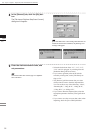
1
From the [File] menu, select [Import],
[Digitizer] and then [Step Scan].
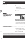
The [File-Import-Digitizer-Step Scan] dialog
box will appear.
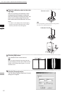
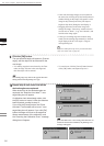
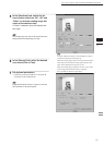
2
Select the desired installation direction
of the VIVID digitizer.
From the [Hardware] tab, check the [Bench
Top Frame set] checkbox, and select the VIVID
digitizer installation direction by clicking the
corresponding [Mounted] radio button.
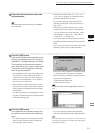
Check the [Auto Scan] checkbox under the
[Hardware] tab.
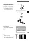
Select [Vertical] if the VIVID digitizer is
mounted vertically, or select [Horizontal] if it is
mounted horizontally.
• The monochrome monitor image currently cap-
tured by the VIVID 910 or VIVID 900 will ap-
pear in the image area of the dialog box.
M
emo
If the VIVID digitizer is mounted horizontally, the pre-
view image will be in portrait form.
After the image is converted to 3D, it will be displayed ac-
cording to the coordinate system of the VIVID.
M
emo
For details of how to save the calibration chart data, refer
to page 87,88.
Operating Procedure
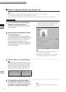
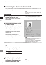
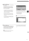
3
Place the object on the rotating stage.
Note
IftheVIVIDdigitizerismountedontheframesethori-
zontally,theobjectwillbeaffectedbyrepeatedreection
ontherotatingstagesurface,preventingcorrectscan
operation.Topreventthis,placeanappropriateitemof
thefollowingthicknessundertheobjecttoraiseit.
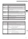
Measurement
Distance
Thickness of Item
600 mm Approx. 30 mm
1000 mm Approx. 20 mm
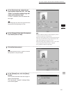
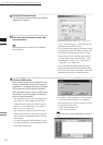
4
To display the object in the middle of the
image area, change the position of the
object or move the rotating stage back
and forth to change the view angle.
M
emo
If necessary, replace the lens attached to the VIVID
digitizer.