75
Ω
ANT /
CABLE
COAXIAL
S-VIDEO
OUT
DIGITAL
AUDIO OUT
AUDIO
OUT
COMPONENT
VIDEO OUT
L
Y
R
CB
CR
DVD
AUDIO OUT
VIDEO OUT
AUDIO IN
VIDEO IN
L
R
L
R
DVD/VCRVCR
ANT-IN
ANT-OUT
AUDIO OUT
VIDEO OUT
AUDIO IN
VIDEO IN
L
R
L
R
DVD/VCR VCR
ANT-IN
ANT-OUT
75
ANT /
CABLE
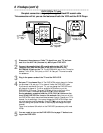
Black RF
coaxial cable
(supplied)
Antenna or
Cable TV
signal
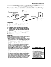
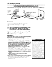
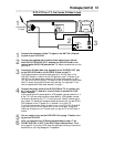
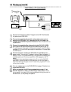
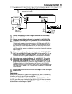
1
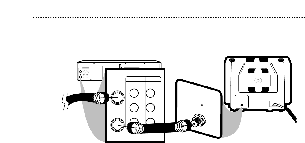
Disconnect the antenna or Cable TV signal from your TV and con-
nect it to the ANT-IN (Antenna In) Jack of your DVD/VCR.
2
Connect the supplied black RF coaxial cable to the ANT-OUT
(Antenna Out) Jack on the back of the DVD/VCR and to the
ANTENNA IN Jack on the TV. The ANTENNA IN jack on the TV may be
labelled TV IN, RF IN, 75Ω (ohm), or ANT. IN. See your TV owner’s manual
for assistance.
3
Plug in the power cords of the TV and the DVD/VCR.
4
Set your TV to channel 3 or 4. The DVD/VCR’s output channel is 3 when
you purchase it. So, set your TV to channel 3 when the DVD/VCR is new.
If you cannot use channel 3 at your TV, you can change the DVD/VCR’s out-
put channel to channel 4. To do so, press the VCR button to put the
DVD/VCR in VCR mode. The green VCR light will be on the front of the
DVD/VCR. Insert a videotape and press PLAY B to start playback.
During playback, press and hold the (VCR) PLAY B button on the
front of the DVD/VCR for three to five seconds. Each time you do this,
the DVD/VCR’s output channel switches between 3 and 4. Change your TV to
channel 3 or 4 accordingly. (You cannot change the DVD/VCR’s output chan-
nel while adjusting tracking manually. Press STOP C to stop play and cancel
manual tracking, then press PLAY B to resume play and change the output
channel.)
There is not a channel 3/4 switch on the DVD/VCR (as customary with most
VCRs).
5
You are ready to turn on the DVD/VCR. Go to page 17 before turn-
ing on the DVD/VCR.
Antenna In Jack
(on back of TV)
example only
8 Hookups (cont’d)
DVD/VCR to TV only
Simplest connection using only the supplied black RF coaxial cable
This connection will let you use the features of both the VCR and the DVD Player.
1
2


