


17 Memory Cassette
185
FX3S Series Programmable Controllers
User's Manual - Hardware Edition
11
Built-in Analog
12
Output Wiring
13
Wiring for
Various Uses
14
Test Run,
Maintenance,
Troubleshooting
15
Other Extension
Units and
Options
16
Display Module
(FX
3S
-5DM)
17
Memory
Cassette
A
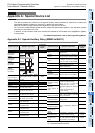
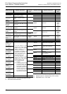
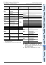
Special Devices
(M8000-, D8000-)
B
Instruction List
C
Discontinued
models
17.7 Memory Cassette <-> PLC (EEPROM Memory) Transfers by Loader Function
17.7 Memory Cassette <-> PLC (EEPROM Memory) Transfers by Loader
Function
The FX3G-EEPROM-32L loader function ([WR] and [RD] key operation) is explained in this section.
• Program transfers (reading/writing) are possible between the memory cassette and the PLC's internal
EEPROM memory.
• The loader function is enabled while the PLC is stopped.
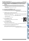
17.7.1 Writing (WR: FX3G-EEPROM-32L -> PLC)
A memory cassette program is written to the PLC's internal EEPROM memory.
Required condition: The PLC must be stopped.
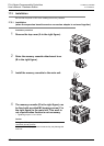
1 Install the memory cassette on the main unit.
Setting the PROTECT switch to ON (on memory cassette's rear face) prevents accidental
overwriting of memory cassette program.
Refer to Section 17.3 for the installation procedure.
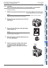
• Verify that the PLC power is OFF, then install the memory cassette on the PLC.
• Turn the PLC power ON.
• Raise the memory cassette's eject lever.
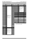
2 Press the [WR] key 1 time.
The [WR] LED lights, and a preparation status is established.
• To cancel, press the [RD] key.
3 Press the [WR] key again.
Writing is executed, and the [WR] LED blinks.
• It takes several seconds to write data to the built-in EEPROM. The [WR] LED flickers while data is written.
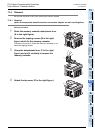
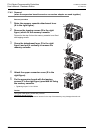
4 Remove the memory cassette from the main unit.
Writing is completed when the [WR] LED goes off.
After turning the PLC power OFF, remove the memory cassette from the PLC.
Refer to Section 17.4 for the removal procedure.
WR LED
WR key