


9 Input Wiring Procedures
9.2 24 V DC input (Sink and source input type)
79
FX3S Series Programmable Controllers
User's Manual - Hardware Edition
1
Introduction
2
Features and
Part Names
3
Product
Introduction
4
Specifications
5
Version and
Peripheral
Devices
6
System
Configuration
7
Installation
8
Preparation and
Power Supply
Wiring
9
Input Wiring
10
High-Speed
Counters
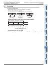
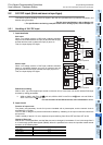
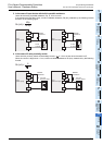
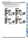
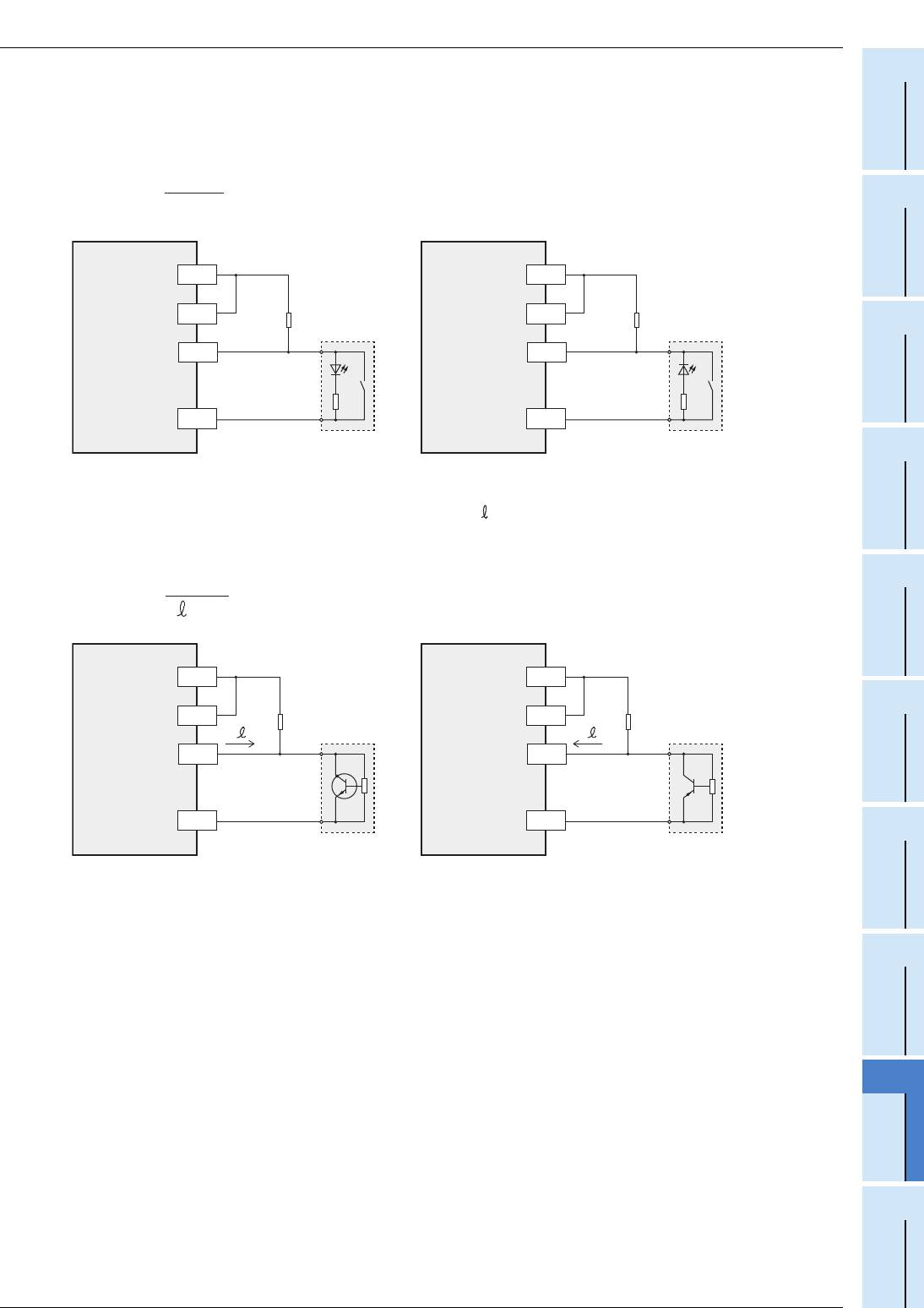
3. In the case of input device with built-in parallel resistance
Use a device having a parallel resistance, Rp, of 15 k or more.
If the resistance is less than 15 k, connect a bleeder resistance, Rb (k), obtained by the following formula
as shown in the following figure.
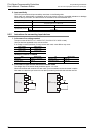
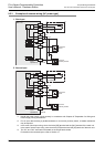
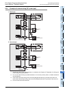
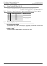
4. In the case of 2-wire proximity switch
Use a two-wire proximity switch whose leakage current, , is 1.5 mA or less when the switch is off.
When the current is larger than 1.5 mA, connect a bleeder resistance, Rb (k), determined by the following
formula.
Rb (kΩ) ≤
4Rp
15-Rp
Rp
Bleeder
resistance
Rb
PLC
(Sink input)
X
0V
24V
S/S
PLC
(Source input)
X
0V
24V
S/S
Rp
Bleeder
resistance
Rb
15 kΩ
or more
15 kΩ
or more
I
Rb (k) ≤
6
I -1.5
Bleeder
resistance
Rb
PLC
(Sink input)
X
0V
24V
S/S
PLC
(Source input)
X
0V
24V
S/S
Bleeder
resistance
Rb
I
Two-wire
proximity sensor
I
Two-wire
proximity sensor