17 Memory Cassette
186
FX3S Series Programmable Controllers
User's Manual - Hardware Edition
17.8 Memory cassette precautions for use
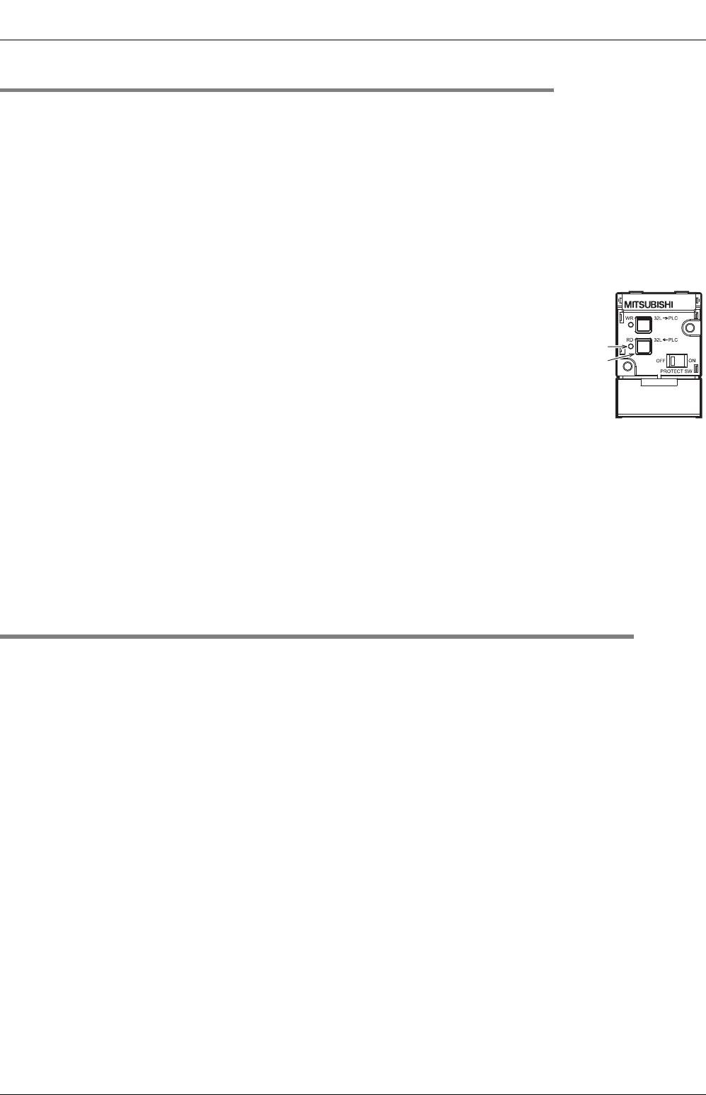
17.7.2 Reading (RD: FX3G-EEPROM-32L <- PLC)
Programs are read from the PLC's internal RAM memory to the memory cassette.
Required condition: The PLC must be stopped, and the PROTECT switch must be OFF.
1 Install the memory cassette on the main unit.
Set the PROTECT switch to OFF.
Refer to Section 17.3 for the installation procedure.
• Verify that the PLC power is OFF, then install the memory cassette on the PLC.
• Turn the PLC power ON.
• Raise the memory cassette's eject lever.
2 Press the [RD] key 1 time.
The [RD] LED lights, and a preparation status is established.
• To cancel, press the [WR] key.
3 Press the [RD] key again.
Reading is executed, and the [RD] LED blinks.
• It takes several seconds to read data from the built-in EEPROM. The [RD] LED flickers while data is read.
4 Remove the memory cassette from the main unit.
Reading is completed when the [RD] LED goes off. After turning the PLC power OFF, remove the
memory cassette from the PLC, then turn the PROTECT switch ON.
Refer to Section 17.4 for the removal procedure.
17.8 Memory cassette precautions for use
1. Tapping screws provided for fixing the memory cassette
Two types of (longer and shorter) M3 tapping screws are packed together with the memory cassette.
Read carefully the installation method described in Section 17.3, and use the proper type.
2. Number of available units
Only one memory cassette may be connected to a FX3S main units.
3. EEPROM memory writing count
10,000 writing operations are permitted at the EEPROM memory.
4. Precaution for file register (D) usage
Writing to the flash memory occurs at each PLC operation cycle if BMOV instructions are used in a
continuous execution format with regard to a file register.
To prevent this, be sure to use "pulse execution format" (BMOVP) instructions.
RD LED
RD key


