


9 Input Wiring Procedures
9.2 24 V DC input (Sink and source input type)
77
FX3S Series Programmable Controllers
User's Manual - Hardware Edition
1
Introduction
2
Features and
Part Names
3
Product
Introduction
4
Specifications
5
Version and
Peripheral
Devices
6
System
Configuration
7
Installation
8
Preparation and
Power Supply
Wiring
9
Input Wiring
10
High-Speed
Counters
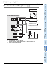
9.2 24 V DC input (Sink and source input type)
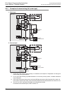
This section explains handling of 24 V DC inputs in the main unit, precautions on input device connection, and
external wiring examples.
For the input specifications, refer to Section 4.3.
For specifications and wiring examples of the built-in analog inputs, refer to Chapter 11.
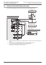
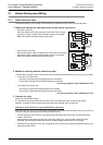
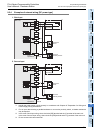
9.2.1 Handling of 24 V DC input
1. Input terminals
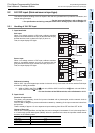
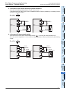
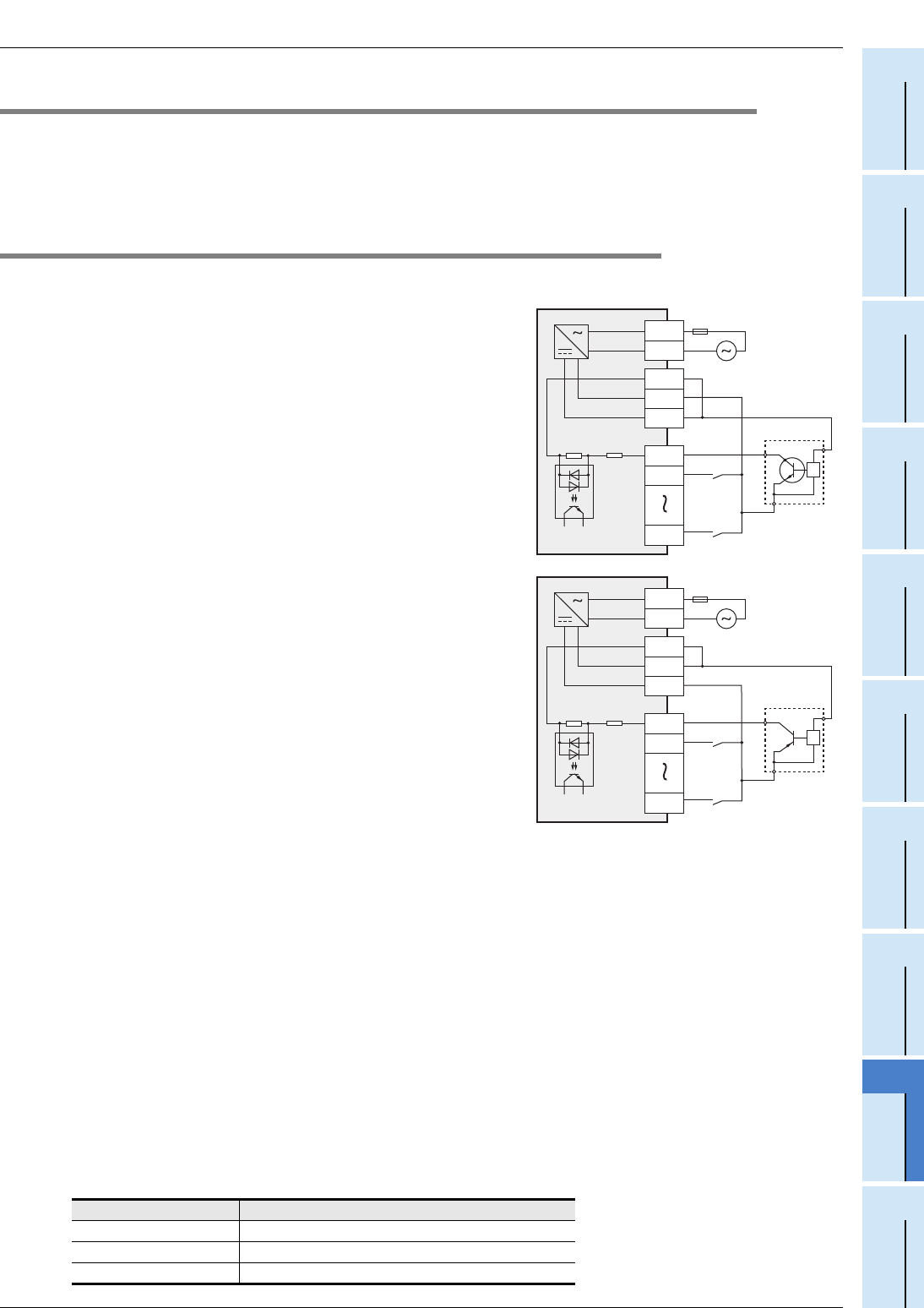
Sink input
When a no-voltage contact or NPN open collector transistor
output is connected between an input (X) terminal and the [0V]
terminal and the circuit is closed, the input (X) turns on.
Then, the input display LED lights.
Source input
When a no-voltage contact or PNP open collector transistor
output is connected between an input (X) terminal and the
[24V] terminal and the circuit is closed, the input (X) turns on.
Then, the input display LED lights.
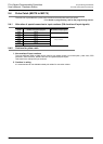
RUN terminal setting
X000 to X017 (up to the largest input number in the main unit
*1
) of the main unit can be used as RUN input
terminals by setting parameters.
*1. X000 to X005 in the FX
3S-10M main unit, X000 to X007 in the FX3S-14M main unit and X000 to
X013 in the FX
3S-20M main unit
For the functions of the RUN terminals, refer to Subsection 14.2.1.
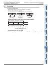
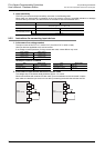
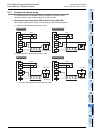
2. Input circuit
Function of input circuit
The primary and secondary circuits for input are insulated with a photocoupler, and the second circuit is
provided with a C-R filter.
The C-R filter is designed to prevent malfunctions caused by chattering of the input contact and noise from
the input line.
There is a delay of approx. 10 ms in response to input-switching from ON to OFF and from OFF to ON.
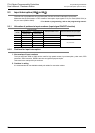
Change of filter time
X000 to X017 have digital filters, and the filter time can be changed in increments of 1 ms in the range from 0
to 15 ms through special data register (D8020). When 0 is specified for the time, the input filter values are set
as shown in the following table.
Input number Input filter value when 0 is specified
X000, X001 10 s
X002 to X007 50 s
X010 to X017 200 s
N
L
X000
X001
X007
*
*Input impedance
100 to 240 V AC
Fuse
24V
0V
S/S
N
L
X000
X001
X007
*
*Input impedance
100 to 240 V AC
Fuse
24V
0V
S/S