


24 Chapter 2. Connecting
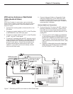
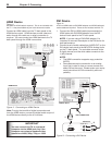
Standard Cable Box, Satellite Receiver,
or Other Device with S-Video
Figure 2
An S-Video cable and stereo audio cables are required. These
are not included with the TV.
1. Connect an S-Video cable from VIDEO OUT on the
cable box or satellite receiver back panel to INPUT
S-VIDEO on the TV back panel.
2. Connect a set of audio cables from AUDIO OUT on
the cable box or satellite receiver back panel to INPUT
AUDIO on the TV back panel. Connect the red cable
to the R (right) channel and the white cable to the L
(left) channel.
Note: Refer to the cable box or satellite receiver
Owner’s Guide for cable or dish antenna connections
to the receiver.
-
3
-
3
7*%&0065
"6%*0065
"6%*0*/
-
3
-
3
7*%&0065
"6%*0065
"6%*0*/
-
3
COMPONENT
YPbPr (480i/480p/720p/1080i)
INPUT
1
2
S-VIDEO
VIDEO
AUDIO-
LEFT/
(MONO)
AUDIO-
RIGHT
1
2
Y
Pb
Pr
AUDIO-
LEFT/
(MONO)
AUDIO-
RIGHT
COMPONENT
YPbPr
(480i/480p/720p/1080i)
INPUT
1
2
S
-
V
I
D
E
O
O
VIDEO
AUDIO-
LEFT/
(MONO)
AUDIO-
RIGHT
1
2
Y
Pb
Pr
AUDIO-
LEFT/
(MONO)
AUDIO-
RIGHT
"OZ47JEFP%FWJDF
57#BDL
1BOFM%FUBJM
$"#-&*/PS
4"5&--*5&*/
*ODPNJOH
$BCMFGSPN
8BMM
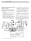
Figure 2. Connecting a device with S-Video
4. Optional: To allow use of the PIP feature with chan-
nels from ANT 1 and the cable box, connect the
incoming terrestrial antenna or cable (not satellite) to
ANT 1 on the TV back panel. A coaxial splitter, avail-
able at most electronic supply stores, may be required
to complete this installation.
Note: To enjoy the benefits of a digital A/V receiver,
connect your cable box or satellite receiver’s digital audio
out to a digital input on your digital A/V receiver.
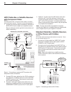
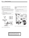
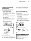
H DTV Cable Box or Satellite Receiver
with Component Video
Figure 1
A coaxial splitter, RCA component video cables, and stereo
audio cables are required. These are not included with the TV.
1. Connect the outside cable or satellite to CABLE IN or
SATELLITE IN on the cable box or satellite receiver.
See your device’s owner’s guide for instructions and
cable compatibility.
:
1S
1C
"6%*0
-
3
COMPONENT
YPbPr (480i/480p/720p/1080i)
INPUT
1
2
S-VIDEO
VIDEO
AUDIO-
LEFT/
(MONO)
AUDIO-
RIGHT
DTV/CABLE/
VHF/UHF
/ANT1 MAIN
DIGITAL
AUDIO
OUTPUT
1
2
Y
Pb
Pr
AUDIO-
LEFT/
(MONO)
AUDIO-
RIGHT
OUTPUT
AUDIO
OUTPUT
RECORD
OUTPUT
DVI
Analog Audio
1 2
VIDEO
AUDIO-
LEFT/
(MONO)
AUDIO-
RIGHT
SER
VICE
POR
T
MONITORLINK™/HDMI
VIDEO 480i/480p/720p/1080i
AUDIO PCM LINEAR
1
2
INPUT
ANT 1
57#BDL
1BOFM%FUBJM
COMPONENT
YPbPr
(480i/480p/720p/1080i)
INPUT
1
2
S
-
V
I
D
E
O
O
VIDEO
AUDIO-
LEFT/
(MONO)
AUDIO-
RIGHT
D
T
V
TVT
/
V/V
C
A
CAC
B
L
E
/
V
H
F
/
F/F
U
H
F
D
I
G
I
T
A
TAT
L
A
U
D
I
O
O
U
T
P
U
T
1
2
Y
Pb
Pr
AUDIO-
LEFT/
(MONO)
AUDIO-
RIGHT
DVI
Analog Audio
1
2
MONIT
ORLINK™/HDMI
VIDEO 480i/480p/720p/1080i
AUDIO PCM LINEAR
1
2
INPUT
ANT 1
5PDBCMFCPY
PSTBUFMMJUF
SFDFJWFS
*ODPNJOH
"OUFOOBPS
$BCMF
)%573FDFJWFSXJUI:1C1S$POOFDUJPOT
$"#-&*/PS
4"5&--*5&*/
Figure 1. Connecting an external HDTV receiver with
component video connections
2. Connect RCA-type cables from the YPrPb outputs on
the cable box or satellite receiver to one of the COM-
PONENT inputs on the TV back panel, matching the
color-coded connections.
3. Connect L (left) and R (right) audio cables from the
cable box or satellite receiver to the corresponding
COMPONENT AUDIO inputs on the TV back panel.