


28 Chapter 2. Connecting
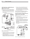
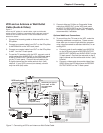
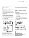
VCR and a Cable Box (Audio and Video
Direct Connections)
Figure 8
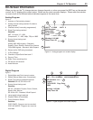
Two coaxial cables, two right and left audio cables, and either
two S-Video cables or two composite video cables are required.
These are not included with the TV but are available at most
electronics stores.
1. Connect the incoming cable to CABLE IN on the cable
box back panel.
2. To allow recording from the cable box to the VCR,
connect one coaxial cable from OUT on the cable box
to ANTENNA IN on the VCR back panel.
3. Connect one set of left and right audio cables from
AUDIO OUT on the cable box back panel to INPUT 1
AUDIO-LEFT (MONO) and AUDIO-RIGHT on the TV
back panel. Connect the red cable to the R (right)
channel and the white cable to the L (left) channel.
Figure 8. Connecting a VCR and Cable Box
COMPONENT
YPbPr (480i/480p/720p/1080i)
INPUT
1
2
-VIDEO
LEFT/
DTV/CABLE/
VHF/UHF
DIGITAL
AUDIO
OUTPUT
1
2
Y
Pb
Pr
AUDIO-
LEFT/
(MONO)
AUDIO-
RIGHT
OUTPUT
AUDIO
OUTPUT
RECORD
OUTPUT
DVI
Analog Audio
1 2
VIDEO
AUDIO-
LEFT/
(MONO)
AUDIO-
RIGHT
SER
VICE
POR
T
MONITORLINK™/HDMI
VIDEO 480i/480p/720p/1080i
AUDIO PCM LINEAR
1
2
INPUT
ANT 1
VIDEO
S-VIDEO
AUDIO-
RIGHT
AUDIO-
LEFT/
(MONO)
COMPONENT
YPbPr
(480i/480p/720p/1080i)
INPUT
1
2
-
V
I
D
E
O
O
LEFT/
D
T
V
TVT
/
V/V
C
A
CAC
B
L
E
/
V
H
F
/
F/F
U
H
F
D
I
G
I
T
A
TAT
L
A
U
D
I
O
O
U
T
P
U
T
1
2
Y
Pb
Pr
AUDIO-
LEFT/
(MONO)
AUDIO-
RIGHT
OUTPUT
AUDIO
OUTPUT
RECORD
OUTPUT
DVI
Analog Audio
1
2
VIDEO
AUDIO-
LEFT/
(MONO)
AUDIO-
RIGHT
SER
VICE
POR
T
MONIT
ORLINK™/HDMI
VIDEO 480i/480p/720p/1080i
AUDIO PCM LINEAR
1
2
INPUT
ANT 1
VIDEO
S
-
-
-
-
V
-
V
V
V
V
V
I
I
I
I
D
D
D
D
E
E
E
E
O
O
O
O
O
O
O
O
AUDIO-
RIGHT
AUDIO-
LEFT/
LEFT/
LEFT/
LEFT/
(MONO)
INPUT
1
2
"/5&//"
065
065
065
065
*/
*/
*/
*/
3
3
-
-.0/0
"6%*0
7*%&0
47*%&0
065065
*/*/
33
33
--
-.0/0-.0/0
"6%*0"6%*0
"/5&//""/5&//"
065065
065065
065065
*/*/
*/*/
*/*/
7*%&07*%&0
47*%&047*%&0
"/5&//"
*/
065
47*%&0
065
7*%&0
065
3
-
"6%*0
"/5&//"
065
065
065
065
*/
*/
*/
*/
3
3
-
-.0/0
"6%*0
7*%&0
47*%&0
"/5&//"
065
065
065
065
*/
*/
*/
*/
3
3
-
-.0/0
"6%*0
7*%&0
47*%&0
065
3
-
"6%*0
065
065
7*%&0
47*%&0
"/5&//"
065
*/
7$3#BDL1BOFM
"UUBDIPOMZPOFUZQF
PGWJEFPDBCMF
"UUBDIPOMZ
POFUZQFPG
WJEFPDBCMF
7JEFP$BCMF
DPNQPTJUFWJEFP
7JEFP$BCMF
DPNQPTJUF
WJEFP
*ODPNJOH
$BCMF
47JEFP$BCMF
47JEFP$BCMF
57#BDL1BOFM
$BCMF#PY
4. Connect either an S-Video or composite video cable
from VIDEO OUT on the cable box to INPUT 1 S-Video
or VIDEO on the TV. Connect only one type of video
cable. S-Video is recommended, if available.
5. Connect one set of left and right audio cables from
AUDIO OUT on the VCR back panel to INPUT 2
AUDIO-LEFT (MONO) and AUDIO-RIGHT on the TV
back panel.
6. Connect either an S-Video or composite video cable
from VIDEO OUT on the VCR to INPUT 2 S-Video or
VIDEO on the TV. Connect only one type of video
cable.
Note: To record TV programs, set the VCR to channel 3
or 4 and on the cable box select the channel to record .
Note: When using this connection configuration, it is pos-
sible to view live cable programs through the VCR Device.
For best picture quality always view live cable programs
directly from the Cable Box Device.