13
13
Part II: Installation
Back Panel Functions
1 2
3
4
5
6 7
8
9
10
11
12
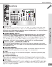
Back Panel
1
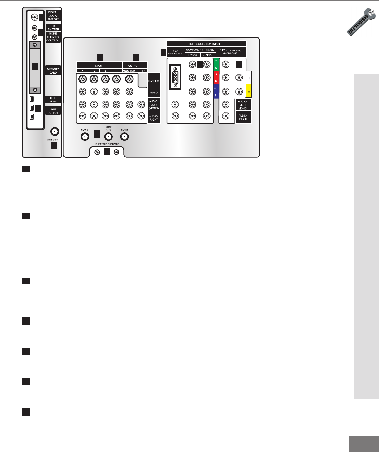
Inputs 1-4
These inputs can be used for the connection of a VCR, Super VHS (S-VHS) VCR, DVD
player, standard satellite receiver, or other A/V device to the TV. Please note that if you
connect to the S-VIDEO terminal, the VIDEO terminal is deactivated. The VIDEO terminal is
active when there is no S-Video connection.
2
Output (Monitor and PIP)
The Monitor Output sends the TV audio and video signals from Ant-A, Ant-B and Inputs
1-5 to a VCR or other analog A/V equipment. It will also send digital audio and video
signals from Ant-DTV and IEEE-1394 products that are not copy protected, and convert
them to analog signals. From VGA, Component 1 and 2 and Input-DTV, no signals will be
sent. The PIP output sends the PIP’s or POP’s audio signal to an ampli er or wi rel ess
headphones. If no PIP or POP is displayed, the PIP output will not send any audio.
3
Antenna (ANT-A, LOOP OUT, and ANT-B)
ANT-A and ANT-B receive analog NTSC signals from VHF/UHF antennas or an analog
NTSC cable system. LOOP OUT sends the ANT-A signal out to another component, such
as a cable box or VCR.
4
IR Emitter-Repeater
Connecting IR emitters here allows the TV to pass IR commands from most IR remote
controls to other A/V devices that are out of range of the remote control.
5
VGA
This input can be used for the connection of a computer. Please see Appendix B, page
73, for signal compatibility.
6
Component Inputs 1-2
These inputs can be used for the connection of A/V equipment with component video
outputs, such as a DVD player. Please see Appendix B, page 73, for signal compatibility.
7
DTV Input
This input is used to connect a DTV receiver, and can be con gur ed f or HDTV s i gnal types
component (YPrPb), RGB sync on green, and RGB plus H&V. Please see Appendix B,
page 73, for signal compatibility.


