


Philips Semiconductors
TDA8752B
Triple high-speed Analog-to-Digital Converter 110 Msps
Product specification Rev. 03 — 21 July 2000 31 of 38
9397 750 07338
© Philips Electronics N.V. 2000. All rights reserved.
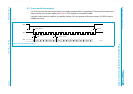
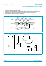
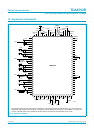
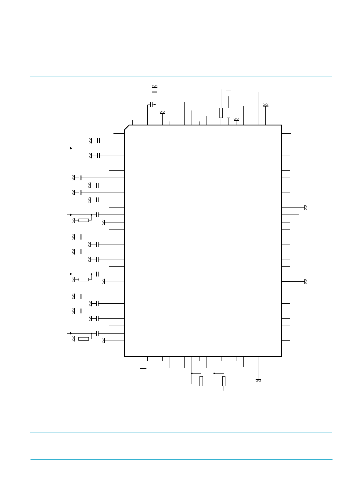
13. Application information
All supply pins have to be decoupled, with two capacitors: one for the high frequencies (approximately 1 nF) and one for the low
frequencies (approximately 100 nF or higher). If a capacitor of 39 nF between pins CZ and CP is not available, use a higher one
as close as possible to this value. Resistors R1 and R2 must be connected: the recommended value is 10 kΩ.
Fig 13. Application diagram.
80
79
78
77
76
75
74
73
72
71
70
69
68
67
66
65
64
63
62
61
60
59
58
57
56
55
54
53
52
51
CKREFO
V
CCO(R)
R7
R6
R5
R4
R3
R2
R1
R0
R1 R2
OGND
R
V
CCO(G)
G7
G6
G5
G4
G3
G2
G1
G0
OGND
G
V
CCO(B)
B7
B6
B5
B4
B3
B2
B1
n.c.
DEC2
V
ref
DEC1
n.c.
RAGC
RBOT
RGAINC
RCLP
RDEC
V
CCA(R)
RIN
AGND
R
GAGC
GBOT
GGAINC
GCLP
GDEC
V
CCA(G)
GIN
AGND
G
BAGC
BBOT
BGAINC
BCLP
BDEC
V
CCA(B)
BIN
RIN
2.5 V
GIN
BIN
AGND
B
n.c.
n.c.
V
CCA(PLL)
CZ
CP
AGND
PLL
V
CCD
CKREF
COAST
CKEXT
INV
HSYNC
CLP
PWDWN
OE
DGND
V
CCO(PLL)
CKADCO
CKBO
OGND
PLL
CKAO
30
29
28
27
26
25
24
23
22
21
20
19
18
17
16
15
14
13
12
11
10
9
8
7
6
5
4
3
2
1
100 99 98 97 96 95 94 93 92 91 90 89 88 87 86 85 84 83 82 81
31 40 4132 4233 4334 4435 4536 4637 4738 4839 49 50
FCE477
TDA8752B
n.c.
4.7
kΩ
4.7
kΩ
150 pF
10 nF
1.5 nF
10 nF
22 nF
4.7 nF
10 nF
10 nF
22 nF
4.7 nF
10 nF
10 nF
22 nF
4.7 nF
10 nF
100 nF
39 nF
100 nF
75 Ω or 50 Ω
100 nF
75 Ω or 50 Ω
n.c.
I
2
C/3W
ADD1
ADD2
TCK
TDO
DIS
SEN
SCL
V
DDD
V
DDD
V
DDD
V
SSD
SDA
n.c.GORn.c.
BORRORn.c.
OGND
B
B0
75 Ω or 50 Ω