


63
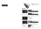
CQ-VD7200U
54
E
N
G
L
I
S
H
62
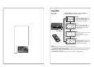
CQ-VD7200U
53
E
N
G
L
I
S
H
Installation Guide (continued)
❏ Before Installation
Warning
¡Do not install the monitor in a location which obstructs
driving, visibility or which is prohibited by applicable
laws and regulations. If the monitor is installed in a
location which obstructs forward visibility or operation
of the air bag or other safety equipment or which inter-
feres with operation of the car, it may cause an accident.
¡Never use bolts or nuts from the car's safety devices for
installation. If bolts or nuts from the steering wheel,
brakes or other safety devices are used for installation of
the monitor, it may cause an accident.
¡Attach the wires correctly. If the wiring is not correctly
performed, it may cause a fire or an accident. In particu-
lar, be sure to run and secure the lead wire so that it
does not get tangled with a screw or the moving portion
of a seat rail.
¡Use with 12 volt DC negative ground car. This unit is
only for use with a 12 volt DC negative ground car. It
cannot be used in large trucks or diesel cars which are
24 volt DC cars. If it is used in the wrong type of car, it
may cause a fire or an accident.
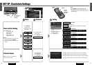
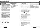
❏ Required Tools
You’ll need a screwdriver and the following:
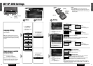
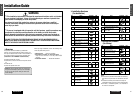
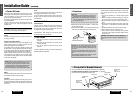
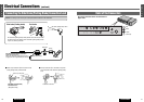
❏ Dashboard Specifications
12 V DC
Test Bulb
Electrical
Tape
Side-Cut
Pliers
Cautions:
¡Use the specified fuse. Be sure to always use the
specified fuse. If a fuse other than the specified fuse
is used, it may cause a fire or an accident.
¡Do not damage the cord by pinching or pulling it.
Do not pull or damage the cord. If the cord is not
treated properly, it will short out or be severed and
may cause a fire or an accident.
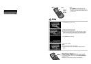
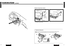
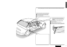
❏ Identify All Leads
The first step in installation is to identify all the car wires
you’ll use when hooking up your LCD monitor.
As you identify each wire, we suggest that you label it using
masking tape and a permanent marker. This will help avoid
confusion when making connections later.
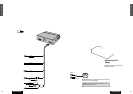
Note: Do not connect the power connector to the display
unit until you have made all connections. If there are no
plastic caps on the hooking wires, insulate all exposed
leads with electrical tape until you are ready to use them.
Identify the leads in the following order.
Power Lead
If your car has a radio or is pre-wired for one:
Cut the connector wires one at a time from the plug (leaving
the leads as long as possible) so that you can work with
individual leads. Turn the ignition on to the accessory posi-
tion, and ground one lead of the test bulb to the chassis.
Touch the other lead of the test bulb to each of the exposed
wires from the cut radio connector plug. Touch one wire at a
time until you find the outlet that causes the test bulb to light.
Now turn the ignition off and then on. If the bulb also turns
off and on, that outlet is the car power lead.
If your car is not wired for an audio unit:
Go to the fuse block and find the fuse port for radio
(RADIO) accessory (ACC) or ignition (IGN).
Battery Lead
If your stereo unit has a yellow lead, you will need to locate
the car's battery lead. Otherwise you may ignore this pro-
cedure. (The yellow battery lead provides continuous power
to maintain a clock or other functions.)
If your car has a radio or is pre-wired for one:
With the ignition and headlights off, identify the car battery
lead by grounding one lead of the test bulb to the chassis
and checking the remaining exposed wires from the cut
radio connector plug.
If your car is not wired for an audio unit:
Go to the fuse block and find the fuse port for the battery,
usually marked BAT.
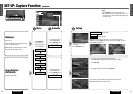
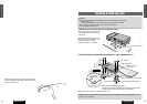
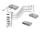
Speakers (not supplied speaker)
Identify the car speaker leads. There are two leads for each
speaker, usually color coded.
A handy way to identify the speaker leads and the speaker
they are connected with is to test the leads using a 1.5 V
AA battery as follows.
Hold one lead against one pole of the battery and stroke the
other lead across the other pole. You will hear a scraping
sound in a speaker if you are holding a speaker lead.
If not, keep testing different lead combinations until you
have located all the speaker leads. When you label them,
include the speaker location for each.
THICKNESS
MIN. 3/16" (4.75 mm)
MAX. 7/32" (5.56 mm)
2-3/32" (53 mm)
7-5/32" (182 mm)