


Pelco Manual C649M (7/99) 17
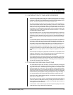
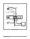
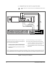
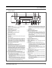
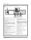
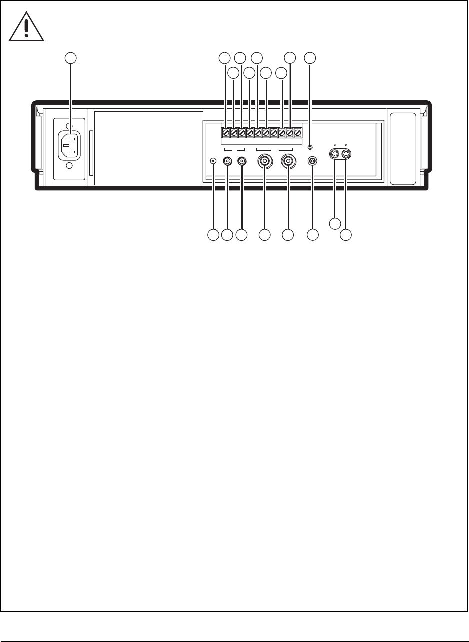
Figure 5. Rear View
5.3 REAR PANEL
1. AC power socket
The power cord plugs into this socket. Insert the cord firmly.
2. SET IN terminal
(Alarm) input terminal to start alarm recording. Connect the
alarm sensor here.
3. RST (reset) IN terminal
Input terminal to stop alarm recording when ALARM REC
DURATION in the Recording Set Up menu is set to MAN1.
Connect the alarm reset switch here. You can also use this
terminal to set the on-screen clock when set to any mode
other than MAN1.
4. REC IN terminal
Input terminal to start/stop recording. You can also use this
terminal for series recording (refer to Section 8.1.5) or syn-
chronous recording (refer to Section 8.1.7).
5. GND (ground) OUT terminal
Connect the ground lead here when a lead connected to
other terminals requires a ground.
6. ALM (alarm) OUT terminal
Output terminal to an external device to indicate an alarm is
being recorded.
7. MODE OUT terminal
Output terminal to indicate the VCR’s mode of operation,
which can be selected by setting the MODE OUT in the Rear
Terminal menu.
8. CLK (clock) OUT terminal
Output terminal to control an external camera switcher, such
as the MX4000 Series Genex™ Multiplexer.
9. CALL OUT terminal
Output terminal to indicate when the tape finishes record-
ing or that there was a problem during recording.
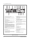
10. RESET button
Press to erase the present time, alarm recording list, power
loss list, and the number of tape uses. Power to the VCR
is cut off while the button is pressed. If there is a tape in
the VCR and the button is released, the power indicator
will light and the tape will fast forward for a few seconds.
The VCR will then turn off.
11. S-VIDEO OUT connector
Output connector for video signal (S-VIDEO connector).
12. S-VIDEO IN connector
Input connector for video signal (S-VIDEO connector).
13. REMOTE jack
The remote control unit is not supplied.
14. VIDEO OUT connector
Output connector for video signal (BNC connector).
15. VIDEO IN connector
Input connector for video signal (BNC connector).
16. AUDIO OUT connector
Audio output connector (RCA pin).
17. AUDIO IN connector
Audio input connector (RCA pin).
18. MIC IN jack
Input jack for a microphone rated at 600-ohms impedance.
NOTE:
Make sure the power cord is unplugged before making any rear terminal connections.
WARNING:
The included power cord is used for 120 VAC, 60 Hz. Never connect the power cord to any
outlet or power supply having a different voltage or frequency.
VIDEO
OUTIN
IN
OUTÉMIC
AUDIO
RESET
REMOTE
SET RST
IN
REC GND ALM MODE CLK CALL
OUT
IN OUT
S-VIDEO
17
16
15
14
13
12
11
10
9
8
7
6
5
4
3
2
1
18