


Pelco Manual C649M (7/99) 25
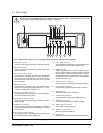
CLOCK OUT Sets the number of frames or fields to record (depending on the
recording mode) at the CLOCK OUT terminal. The default is
REC.
1. First, set the recording mode for the CLOCK OUT pulse
output in the Rear Terminal menu.
• REC – When recording in any mode.
• T/L-REC – When recording in time-lapse mode
(L18H, L24H, 48H, 72H, 96H, 120H, 168H, or 0H).
2. Second, select the frequency interval by turning the
SHUTTLE ring. When you turn the JOG dial, the display
switches in the following order: 1, 2, 3, 4, 5, 10, 15, 20,
25, 30, 50, 60, F (field), 1. The numbers from 1 to 60
indicate the number of frames in 2H or 6H recording mode
or the number of fields in time-lapse recording mode. One
frame consists of two fields. One field is selected when it
is set to “F” (field).
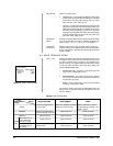
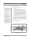
MODE OUT Sets the state in which the signal output at the MODE OUT
terminal is switched to active. When you turn the JOG dial, the
display switches in the following order: REC (recording), PLAY
(playback), POWER (power on), TAPE IN (tape inserted),
TAPE REMAIN (three minutes in 2H mode before the tape
ends), CLOCK ADJ (output the signal for one second when the
clock indicates 00[min]:00[sec]), REC. The default is REC.
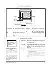
REC IN Sets the REC IN terminal’s operation mode. The default is
SERIES.
• SERIES – Recording starts when the REC IN terminal is
short-circuited to ground or a low-level voltage (0 to +1.6V)
is applied.
• REC-START/STOP – Recording starts when the REC IN
terminal is short-circuited to ground or a low-level voltage
(0 to +1.6V) is applied. Recording stops if this connection
is removed.
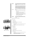
• SYNC REC – The video signals from 3 or 13 cameras
can be recorded separately by connecting a switcher.
(Synchronous recording is available when recording in
L18H or L24H mode.) Synchronous recording is explained
(and the procedure listed) in Section 8.1.7.
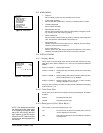
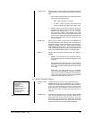
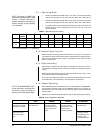
6.9 MAINTENANCE MENU
POWER LOSS To display the power loss list, turn the JOG dial to select
LIST POWER LOSS LIST. Turn the SHUTTLE ring to the right to
display the list. Power failure start times are stored in memory,
so you can confirm when they occurred. Up to three power
failure start times will be displayed. If there were more than
three, the first and last two power failure start times will be
displayed.
ALARM LIST To display the alarm list, turn the JOG dial to select ALARM
LIST. Turn the SHUTTLE ring to the right to display the list.
Alarm record start times are stored in memory, so you can
confirm when they occurred. Up to three alarm record start
times will be displayed. If there were more than three, the first
and last two alarm record start times will be displayed.
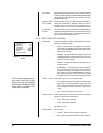
Figure 14. Maintenance Menu
0
0H
<
MAINTENANCE
>
POWER LOSS LIST
ALARM LIST
ALL MENU INITIALIZE
POWER LOSS LIST CLEAR
ALARM LIST CLEAR
<
REPEAT REC TIMES
>
<
ELAPSED TIME
>