10 Pelco Manual C681M-D (2/02)
CLOCK ADJ
REC
POWER ON
POWER OFF
ALARM OUT
MODE OUT
CALL OUT
CALL OUT GND
GND
DC 5V OUT
MAX 30mA
1
MIC
IN
OUT
23456789
1
RS-232C
234
1
GND
23456789
CAMERA IN
AUDIO
CAMERA OUT
ALARM IN
56789
ON OFF
SCSI
Y/C
VIDEO
OUT
GND
GND
GND
1
3
5
6
2
4
7
8
9
10 11
RESET
SCSI
TERMINATION
12345678910111213141516
CAMERA IN
12345678910111213141516
CAMERA OUT
VIDEO OUT
Y/C
CLOCK ADJ
REC
POWER ON
POWER OFF
ALARM OUT
MODE OUT
CALL OUT
CALL OUT GND
GND
GND
DC 5V OUT
MAX 30mA
GND
RS-232C
ETHERNET
RESET
ON OFF
SCSI
SCSI
TERMINATION
IN
OUT
AUDIO
MIC
GNDGND
16
15
14
13
12
11
10
9
8
7
6
5
4
3
2
1
ALARM IN
1
3
5
6
2
4
9
10
11
78
12
00510
18. REMOTE communication button and indicator lights
(DX3016 Models Only)
Not used.
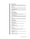
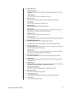
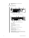
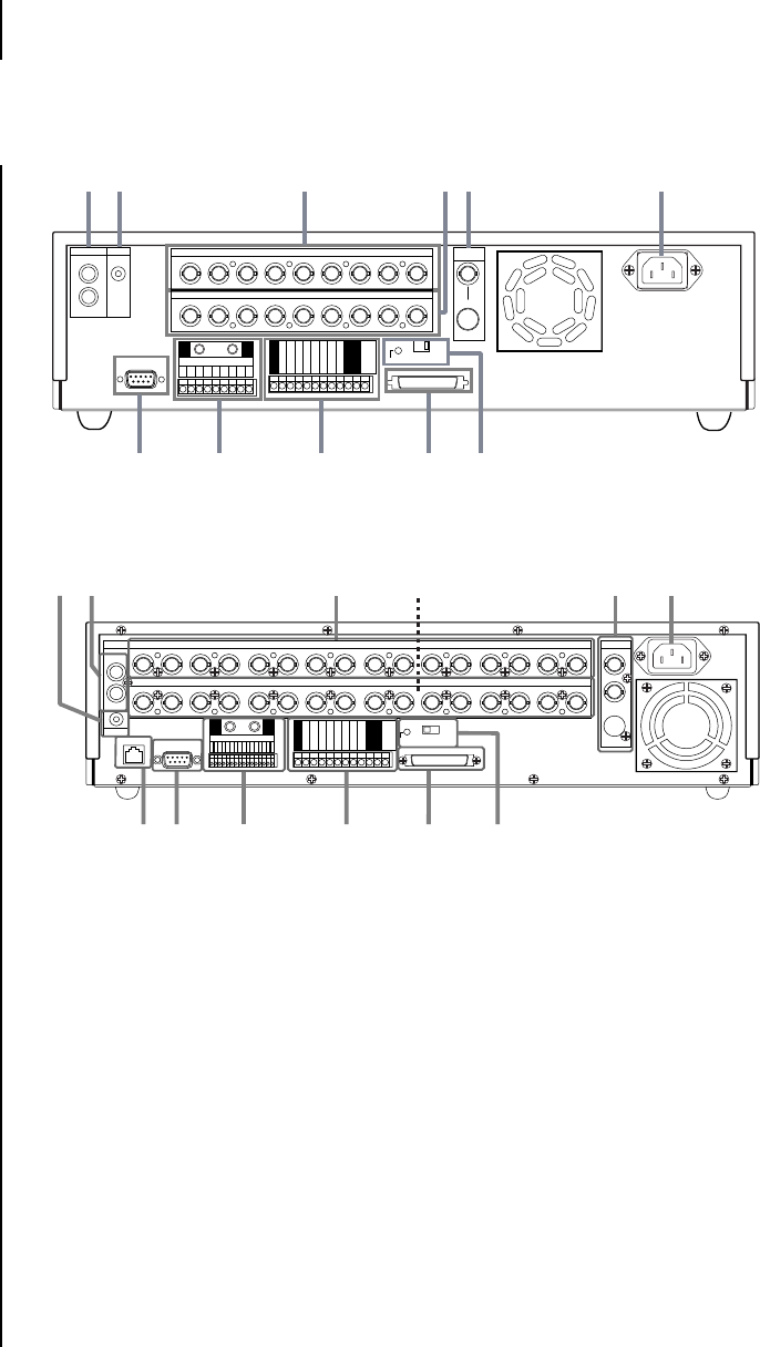
REAR PANEL CONNECTORS
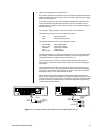
Figure 3. Rear Panel Connectors, DX3009 Models
Figure 4. Rear Panel Connector, DX3016 Models
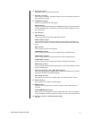
1. Audio connectors
AUDIO IN connector
This is an RCA input connector for an audio signal.
AUDIO OUT connector
This is an RCA output connector for an audio signal.
2. MIC jack
This is an input connector for a microphone (600-ohm impedance).
3. CAMERA IN connectors
These are BNC input connectors for cameras.
4. CAMERA OUT connectors
These are BNC output (looping) connectors for cameras.
5. VIDEO OUT connectors
There are two video output connectors: a BNC standard composite video output con-
nector and an SVHS connector for separate luminance and chrominance (Y/C) signals.
Both connectors can be used at the same time.


