Pelco Manual C681M-D (2/02) 11
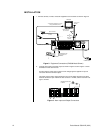
6. AC power socket
This socket is for a 100-240 VAC power cord.
7. RS-232C connector
This is where a PelcoNet™ Transmission System can be connected for remote view-
ing and control of cameras.
8. ALARM IN terminals
These are input terminals for alarm signals.
GND terminals
These are earth ground terminals for the ALARM IN terminals. Use only the terminal
screws provided with this unit; otherwise, the recorder could be damaged or connec-
tions may be poor.
9. I/O terminals
GND terminals
These are ground terminals for the input/output terminals.
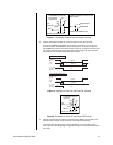
CLOCK ADJ terminal
This is an input terminal to set the time display. The time display is adjusted to the
nearest hour (00 minutes, 00 seconds) when this terminal receives the clock adjust
signal.
REC terminal
This is an input terminal to start recording.
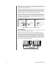
POWER ON terminal
This is an input terminal to turn on the recorder through a peripheral device.
POWER OFF terminal
This is an input terminal to turn off the recorder through a peripheral device.
ALARM OUT terminal
This is an output terminal to indicate that an alarm recording is being made.
MODE OUT terminal
This is an output terminal to indicate the recorder’s current mode. Select the mode in
the Rear Terminal menu.
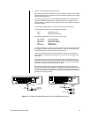
CALL OUT terminal / CALL OUT GND terminal
This is an isolated (optically coupled) output to indicate information such as the hard
disk drive is full. Refer to the
Warnings
section.
DC 5V OUT terminal
This terminal is for direct current voltage output. The maximum current is 30 mA.
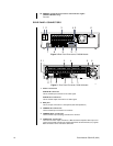
10. SCSI connector
This connector is for peripheral recording devices.
11. RESET button
When pressed, the present time is erased, the system is reset, and the power is
turned off.
SCSI TERMINATION switch
When set to ON, the termination function is enabled; when set to OFF, the termination
function is disabled. Set the switch ON when nothing is connected to the SCSI connector.
12. Ethernet connector (DX3016 Models Only)
Not used.


