Pelco Manual C681M-D (2/02) 15
CLOCK ADJ
REC
POWER ON
POWER OFF
ALARM OUT
MODE OUT
CALL OUT
CALL OUT GND
DC 5V OUT
MAX 30mA
RS-232C
123456789
ALARM IN
RESET
ON OFF
SCSI
TERMINATION
SCSI cable
Peripheral
copy/archive
device
Te rminator
GND GND
GND
GND
GND
SCSI
terminal
123456789
1234
CAMERA IN
CAMERA OUT
56789
Y/C
OUT
VIDEO
SCSI
MIC
IN
OUT
AUDIO
01147
CLOCK ADJ
REC
POWER ON
POWER OFF
ALARM OUT
MODE OUT
CALL OUT
CALL OUT GND
DC 5V OUT
MAX 30mA
123456789
ALARM IN
RESET
ON OFF
SCSI
SCSI
TERMINATION
SCSI cable
SCSI cable
Peripheral
hard disk
drives
Te rminator
SCSI cable
GND GND
GND
GND
GND
SCSI
terminal
MIC
IN
OUT
AUDIO
RS-232C
123456789
1234
CAMERA IN
CAMERA OUT
56789
Y/C
OUT
VIDEO
011487
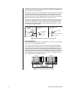
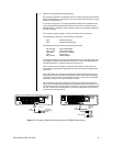
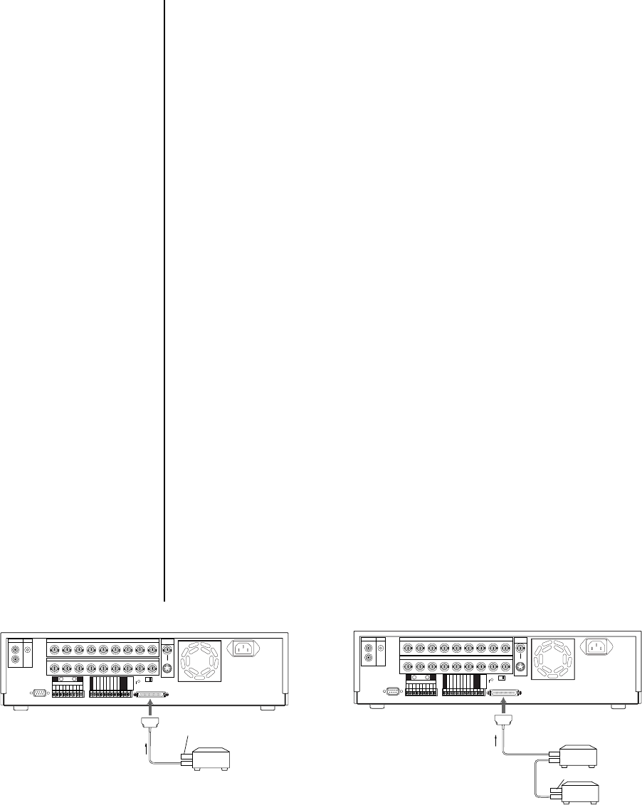
5. Optional. Connect peripheral recording devices.
By connecting peripheral recording devices to the recorder through the SCSI interface
(SCSI-II half-pitch 50-pin), storage space can be increased and archiving and copying
functions can be performed.
To increase storage space, up to two (DX3009-060, DX3016-060, and DX3016-120)
or three (DX3009-030) peripheral hard disk drives (maximum of 34 GB per unit for
DX3009 models or 103 GB per unit for DX3016 models) can be added to supplement
the built-in hard disk.
For archiving or copying functions, a tape or disk device can be connected.
The following tape devices can be connected to the recorder:
Pelco DX3000-D25 (drive)
Pelco DX3000-T25 (blank tape)
The following disk devices can be connected to the recorder:
MO (640 MB) Fujitsu SMB-640WF
MO (1.3 GB) Fujitsu SMB-1300W
DVD-RAM Panasonic LF-D200JD
HDD SCSI-IF Type
Zip (250 MB) IOMEGA Z250S
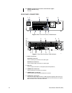
Connections between the recorder and peripheral devices are made with SCSI cables
(not supplied). As SCSI cables differ with each device, check for the appropriate pin
arrangement before use. Cables must not exceed 3 feet (1 m).
On the rear panel of the recorder is a SCSI termination switch. Set the switch ON
when nothing is connected the SCSI connector. Set to OFF when connecting periph-
eral devices.
Correct termination is necessary to maintain proper electrical connections to the pe-
ripheral devices. Make sure that the last peripheral device is terminated. (Depending
on the device, the terminator may be built into the device. In this case, set the built-in
terminator correctly.) Use an active terminator for SCSI.
Set the SCSI ID number of the peripheral recording device. Refer to the operation
manual of each peripheral recording device for setting the SCSI ID Number. Use ID1-3
for hard drives, ID4 for an archive device, and ID5 for a copy device. On DX3016 mod-
els, also use ID4 when a hard disk drive is connected for repeated backup recording
(considered an archiving function).
Figure 12. Connecting Peripheral Recording Devices (DX3009 Models Shown)


