


22 C1680M (1/06)
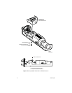
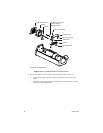
11. Connect power, fiber optic, and video cabling to the transmitter by doing the following:
a. Insert the power cable through the gland or conduit on the bottom of the enclosure, and
then connect the cable to the power connector on the transmitter.
b. Insert the fiber optic cable through the gland or conduit on the bottom of the enclosure,
and then do the following:
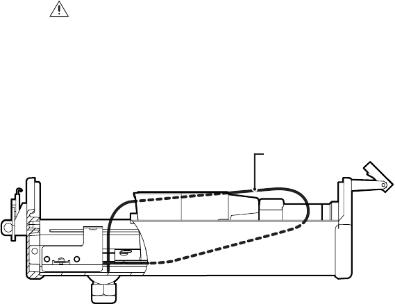
WARNING: When routing the fiber optic cable, be careful not to bend the fiber
at a sharp angle. Doing so breaks the fiber.
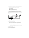
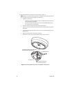
(1) Carefully loop the cable around the camera (refer to Figure 12).
(2) Connect the cable to the fiber optic connector on the transmitter.
c. Using the coaxial cable supplied with the transmitter, connect the cable to the BNC
connector on the transmitter and on the camera.
NOTE: For additional information about connections to the transmitter, refer to the Connections
section.
Figure 12. Routing Fiber Optic Cable in EH3512/EH3515 Enclosure
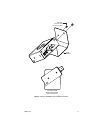
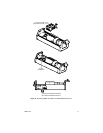
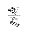
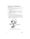
12. Reinstall the enclosure accessories as follows:
a. Reattach the rear heater bracket, blower, and heater to the enclosure using the two
6-32 x 1.5-inch Phillips pan head screws and lock washers (refer to Figure 13).
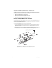
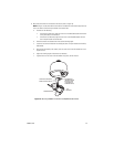
b. Attach the PC board and related accessories as follows (refer to Figure 14):
(1) Attach the PC board and the cover bracket to the left EH3500 bracket using one
6-32 x 0.5-inch Phillips pan head screw and lock washer and two nylon washers.
(2) Attach the other side of the PC board to the right EH3500 bracket using one
6-32 x 0.5-inch Phillips pan head screw and lock washer and two nylon washers.
(3) Snap the PC board cover into place.
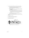
13. Reconnect power to the camera.
14. Close the lid of the enclosure, and latch the lid.
15. Reconnect power to the enclosure.
FIBER OPTIC CABLE