


14
English
L
R
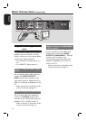
DIGITAL ANTENNA
RS-232
AUDIO OUTPUTVIDEO OUTPUT
COMPONENT
S-VIDEO
CVBS
PCM / DOLBY DIGITAL
COAXIAL
Manufactured under license from
Dobly Laboratories. “Dolby” and
the double-D symbol are
trademarks of Dolby Laboratories.
OPTICAL
ANALOG
HDMI
Y
L
R
P
b
Pr
1 2
RF IN RF IN
RF OUTTO TV
LOOP THROUGH
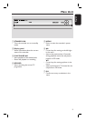
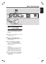
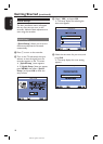
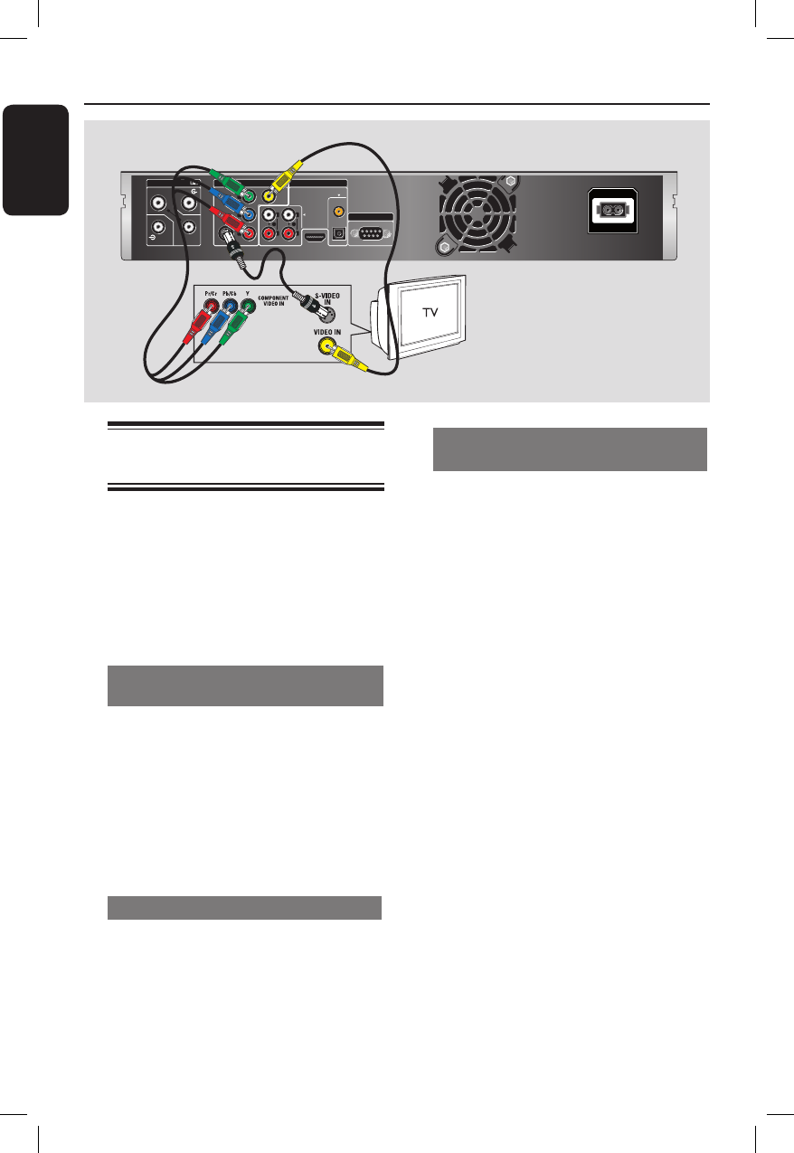
Basic Connections (continued)
Step 2: Connecting the video
cable
This connection enables you to view the
playback from this recorder. You only
need to choose one of the options below
to make your video connection.
– For a standard TV, follow option 1, 2
or 3.
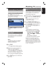
– For a HDMI TV, follow option 4.
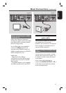
Option 1: Using the Video (CVBS)
socket
Use a composite video cable (yellow) to
connect the VIDEO OUTPUT -
CVBS socket on the recorder to the
video input socket (or labelled as A/V In,
Video In, Composite or Baseband) on the
TV.
– Audio connection is required in order
to hear the sound, see page 15.
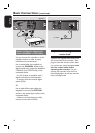
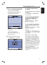
Option 2: Using the S-Video socket
Use an S-video cable (not supplied) to
connect the S-VIDEO socket on the
recorder to the S-Video input socket (or
labelled as Y/C or S-VHS) on the TV.
– Audio connection is required in order
to hear the sound, see page 15.
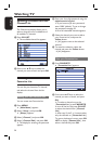
Option 3: Using the COMPONENT
Y P
B
P
R
sockets
Use the component video cables (red/
blue/green) to connect the VIDEO
OUTPUT-COMPONENT - Y P
B
P
R
sockets on the recorder to the
corresponding component video input
sockets (or labelled as Y P
b
/C
b
P
r
/C
r
or
YUV) on the TV.
– Audio connection is required in order
to hear the sound, see page 15.
Option 1
Option 2
Option 3